


DE2-70 User Manual
87
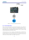
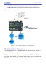
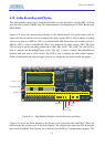
6.10 Audio Recording and Playing
This demonstration shows how to implement an audio recorder and player using the DE2-70 board
with the built-in Audio CODEC chip. This demonstration is developed based on SOPC Builder and
NIOS II IDE.
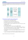
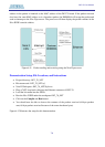
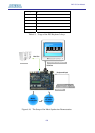
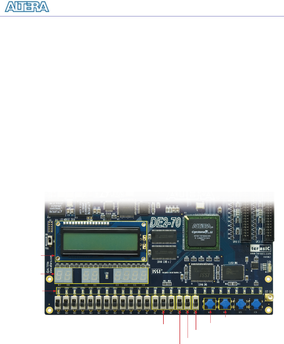
Figure 6.18 shows the man-machine interface of this demonstration. Two push buttons and six
toggle switches are used for users to configure this audio system: SW0 is used to specify recording
source to be Line-in or MIC-In. SW1 is to enable/disable MIC Boost when the recoding source is
MIC-In. SW2 is used to enable/disable Zero-Cross Detection for audio playing. SW3, SW4 and
SW5 are used to specify recording sample rate as 96K, 48K, 44.1K, 32K, or 8K. The 16x2 LCD is
used to indicate the Recording/Playing status. The seg7 is used to display Recording/Playing
duration with time unit in 1/100 second. The LED is used to indicate the audio signal strength.
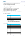
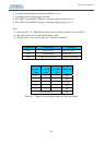
Table 6.4 summarizes the usage of toggle switches for configuring the audio recorder and player.
Record/Play Status
Signal Strength
Record/Play Duration
Sample rate
Audio Source
Play
Record
MIC Boost
Zero-Cross Detect
Figure 6.18. Man-Machine Interface of Audio Recorder and Player.
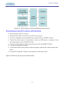
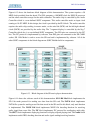
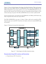
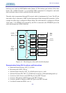
Figure 6.19 shows the block diagram of the design of the Audio Recorder and Player. There are
hardware part and software part in the block diagram. The software part means the Nios II program
that stored in SSRAM. The software part is built by Nios II IDE in C programming language. The