


DE2-70 User Manual
66
Chapter 6
Examples of Advanced Demonstrations
This chapter provides a number of examples of advanced circuits implemented on the DE2-70
board. These circuits provide demonstrations of the major features on the board, such as its audio
and video capabilities, and USB and Ethernet connectivity. For each demonstration the Cyclone II
FPGA (or EPCS16 serial EEPROM) configuration file is provided, as well as the full source code in
Verilog HDL code. All of the associated files can be found in the DE2_70_demonstrations folder
from the DE2-70 System CD-ROM. For each of demonstrations described in the following
sections, we give the name of the project directory for its files, which are subdirectories of the
DE2-70_demonstrations folder.
Installing the Demonstrations
To install the demonstrations on your computer, perform the following
1. Copy the directory DE2_70_demonstrations into a local directory of your choice. It is
important to ensure that the path to your local directory contains no spaces –
otherwise, the Nios II software will not work.
6.1 DE2-70 Factory Configuration
The DE2-70 board is shipped from the factory with a default configuration that demonstrates some
of the basic features of the board. The setup required for this demonstration, and the locations of its
files are shown below.
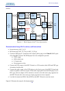
Demonstration Setup, File Locations, and Instructions
• Project directory: DE2_70_Default
• Bit stream used: DE2_70_Default.sof or DE2_70_Default.pof
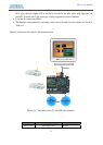
• Power on the DE2-70 board, with the USB cable connected to the USB Blaster port. If
necessary (that is, if the default factory configuration of the DE2-70 board is not currently
stored in EPCS16 device), download the bit stream to the board by using either JTAG or AS
programming
• You should now be able to observe that the 7-segment displays are displaying a sequence of
characters, and the red and green LEDs are flashing. Also, Welcome to the Altera DE2-70
is shown on the LCD display