


Introduction
1-8
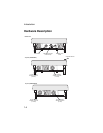
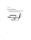
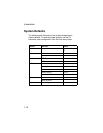
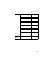
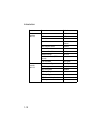
System Configuration
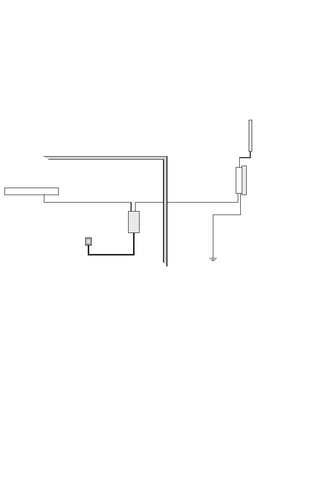
At each location where a unit is installed, it must be connected to
the local network using the power injector module. The following
figure illustrates the system component connections.
Indoor Outdoor
LAN Switch
AC Power
Power
Injector
Wireless Bridge Unit
Ground Wire
Ethernet Cable Ethernet Cable
ExternalAntenna
RF Coaxial Cable