


Cables and Pinouts
C-4
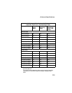
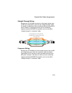
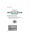
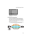
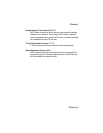
8-Pin DIN Connector Pinout
The Ethernet cable from the power injector connects to an 8-pin
DIN connector on the wireless bridge. This connector is
described in the following figure and table.
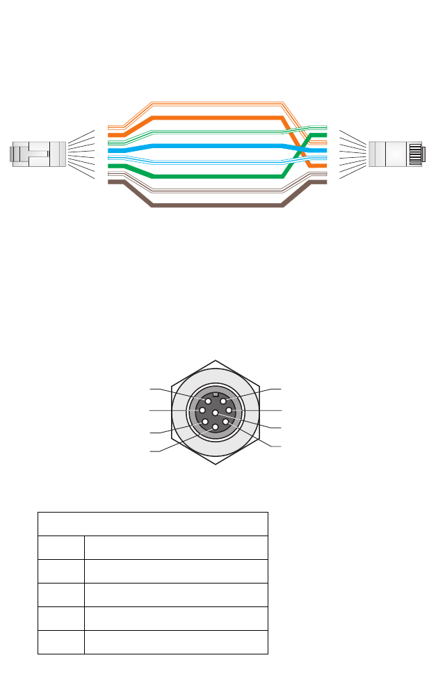
8-Pin DIN Ethernet Port Pinout
Pin Signal Name
1 Transmit Data plus (TD+)
2 Transmit Data minus (TD-)
3 Receive Data plus (RD+)
4 +48 VDC power
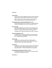
White/Orange Stripe
Orange
White/Green Stripe
1
2
3
4
5
6
7
8
1
2
3
4
5
6
7
8
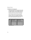
EIA
/
TIA568B RJ-45 Wiring
S
tandard
10/100BASE-TX Crossover Cable
End A
End B
Green
Blue
White/Blue Stripe
Brown
White/Brown Stripe
1
7
2
3
4
5
8
6