


Hardware Installation
4-10
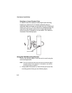
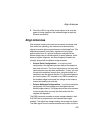
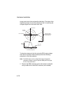
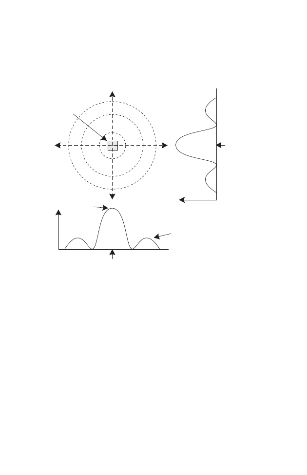
strong central main lobe and smaller side lobes. The object of the
alignment process is to set the antenna so that it is receiving the
strongest signal from the central main lobe.
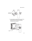
To align the antennas in the link using the RSSI output voltage,
start with one antenna fixed and then perform the following
procedure on the other antenna:
Note: The RSSI output can be configured through management
interfaces to output a value for specific WDS ports. See page
6-54 for more information.
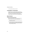
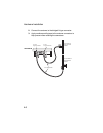
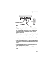
1. Remove the RSSI connector cover and connect a voltmeter
using a cable with a male BNC connector (not included).
Main Lobe
Maximum
Horizontal Scan
Vertical Scan
RSSI
Voltage
Side Lobe
Maximum
RSSI Voltage
Remote
Antenna
Maximum Signal Strength Position
for HorizontalAlignment
Maximum Signal
Strength Position for
Vertical Alignment