


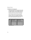

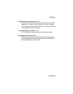

8-Pin DIN Connector Pinout
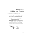
C-5
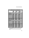
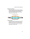
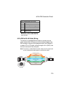
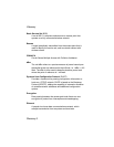
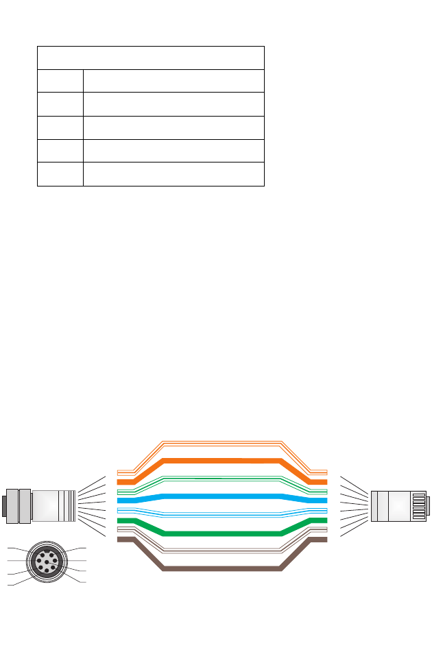
8-Pin DIN to RJ-45 Cable Wiring
To construct an extended Ethernet cable to connect from the
power injector’s RJ-45 Output port to the wireless bridge’s 8-pin
DIN connector, follow the wiring diagram below. Use Category 5
or better UTP or STP cable, maximum length 100 m (328 ft), and
be sure to connect all four wire pairs.
Note:To construct a reliable Ethernet cable, always use the proper tools
or ask a professional cable supplier to construct the cable.
5 +48 VDC power
6 Receive Data minus (RD-)
7 Return power
8 Return power
Note: The “+” and “-” signs represent
the polarity of the wires that make up
each wire pair.
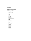
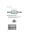
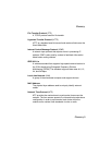
8-Pin DIN Ethernet Port Pinout
Pin Signal Name
White/Orange Stripe
Orange
White/Green Stripe
Green
1
2
3
4
5
6
7
8
1
2
3
4
5
6
7
8
8-Pin DIN
Female
RJ-45
1
7
2
3
4
5
8
6
White/Blue Stripe
White/Brown Stripe
Brown
Blue
8-Pin DIN Female
Front View