Chapter 2 System Overview 13
gain access to the disk drives, power supplies, and Fan Tray 0. If the media door is
locked and the power supply access panel is in place, you will not be able to gain
access to the power supplies, disk drives, and Fan Tray 0—even if the PCI access
panel is unlocked.
Note – The same key operates the security lock, the system control switch (see
“System Control Switch” on page 15), and the top panel lock for the PCI and CPU
access panels.
The standard system is configured with two power supplies, which are accessible
from the front of the system. LED indicators display power status. See “LED Status
Indicators” on page 13 for additional details.
LED Status Indicators
Several LED status indicators on both the front and back panels provide general
system status, alert you to system problems, and help you to determine the location
of system faults.
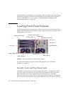
At the top left of the system as you look at its front are three general system LEDs.
Two of these LEDs, the system Fault LED and the Power/OK LED, provide a snapshot
of the overall system status. The Locator LED helps you to locate a specific system
quickly, even though it may be one of dozens or even scores of systems in a room.
The front panel Locator LED is at the far left in the cluster. The Locator LED is lit by
command from the administrator. For instructions, see “How to Operate the Locator
LED” on page 168.
Other LEDs located on the front of the system work in conjunction with specific fault
LED icons. For example, a fault in the disk subsystem illuminates the disk drive
Fault LED in the center of the LED cluster that is next to the affected disk drive.
Since all front panel status LEDs are powered by the system’s 5-volt standby power
source, Fault LEDs remain lit for any fault condition that results in a system
shutdown.
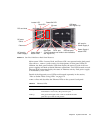
Locator, Fault, and Power/OK LEDs are also found at the upper-left corner of the
back panel. Also located on the back panel are LEDs for the system’s two power
supplies and RJ-45 Ethernet ports.
See
FIGURE 2-1 and FIGURE 2-3 for locations of the front panel and back panel LEDs.
During system startup, LEDs are toggled on and off to verify that each one is
working correctly.
The following tables list and describe the LEDs on the front panel: system LEDs, fan
tray LEDs, and hard disk drive LEDs.


