Chapter 3 Hardware Configuration 31
Configuration Rules
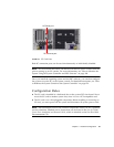
■ DIMMs must be added four-at-a-time within the same group of DIMM slots;
every fourth slot belongs to the same DIMM group.
■ Each group used must have four identical DIMMs installed—that is, all four
DIMMs must be from the same manufacturing vendor and must have the same
capacity (for example, four 512-Mbyte DIMMs or four 1-Gbyte DIMMs).
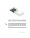
For guidelines and complete instructions on how to install DIMMs in a
CPU/Memory board, see the Sun Fire V490 Server Parts Installation and Removal
Guide.
Note – Do not attempt to access any internal components unless you are a qualified
service technician. Detailed service instructions can be found in the Sun Fire V490
Server Parts Installation and Removal Guide, which is included on the Sun Fire V490
Documentation CD.
About the PCI Cards and Buses
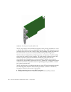
All system communication with storage peripherals and network interface devices is
mediated by two Peripheral Component Interconnect (PCI) bridge chips, located on
the system’s centerplane. Each bridge chip manages communication between the
system’s main interconnect bus and two PCI buses, giving the system a total of four
separate PCI buses. The four PCI buses support up to six PCI interface cards and
four centerplane devices.
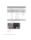
TABLE 3-2 describes the PCI bus characteristics and maps each bus to its associated
bridge chip, integrated devices, and PCI card slots. All slots comply with PCI Local
Bus Specification Revision 2.1.
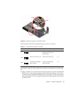
CPU 1 Slot B B0, B1
CPU 2 Slot A A0, A1
CPU 3 Slot B B0, B1
TABLE 3-1 Association Between Processors and DIMM Groups (Continued)
CPU Number CPU/Memory Slot
Associated Local DIMM
Groups


