


Chapter 2 System Overview 17
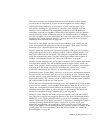
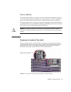
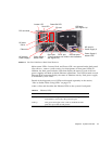
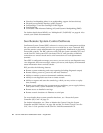
FIGURE 2-3 Sun Fire V490 Server Back Panel Features
Main system LEDs—Locator, Fault, and Power/OK—are repeated on the back panel.
(See
TABLE 2-1, TABLE 2-2, and TABLE 2-3 for descriptions of front panel LEDs.) In
addition, the back panel includes LEDs that display the status of each of the two
power supplies and both on-board Ethernet connections. Two LEDs located on each
Ethernet RJ-45 connector display the status of Ethernet activity. Each power supply
is monitored by four LEDs.
Details of the diagnostic use of LEDs are discussed separately in the section,
“How to Isolate Faults Using LEDs” on page 172.
TABLE 2-5 lists and describes the Ethernet LEDs on the system’s back panel.
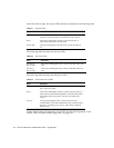
TABLE 2-5 Ethernet LEDs
Name Description
Activity This amber LED lights when data is either being
transmitted or received by the particular port.
Link Up This green LED lights when a link is established at the
particular port with its link partner.
SC card
USB ports
Serial port FC-AL port
AC input for
SC ports:
Serial
Ethernet
Power Supply 1
status LEDs
Power Supply 0
status LEDs
Power/OK LEDLocator LED
Ethernet ports
PCI card slots
Fault LED
AC input for
Power Supply 0
Power Supply 1
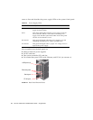
(The ports above not visible in this illustration;
see Figure 2-4.)
(see Figure 2-4)