Dimension ES-2008 Ethernet Switch
Hardware Description and Installation 2-1
Chapter 2
Hardware Description and
Installation
This chapter describes the switch hardware and installation
2.1 Hardware Installation
The switch is suitable for an office environment where it can be placed on a desktop.
Step 1. Make sure the switch is clean and dry.
Step 2. Attach the supply rubber feet to the bottom of the switch.
Step 3. Set the switch on a smooth and sturdy flat space strong enough to support the
weight of the switch and the connected cables. Make sure there is a power
outlet nearby.
Step 4. Make sure there is enough clearance around the switch to allow air circulation
and the attachment of cables and the power cord.
Do not block the ventilation holes. Leave space between switches
when stacking.
2.2 Hardware Connections
2.2.1 Front Panel
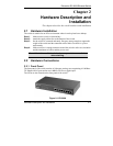
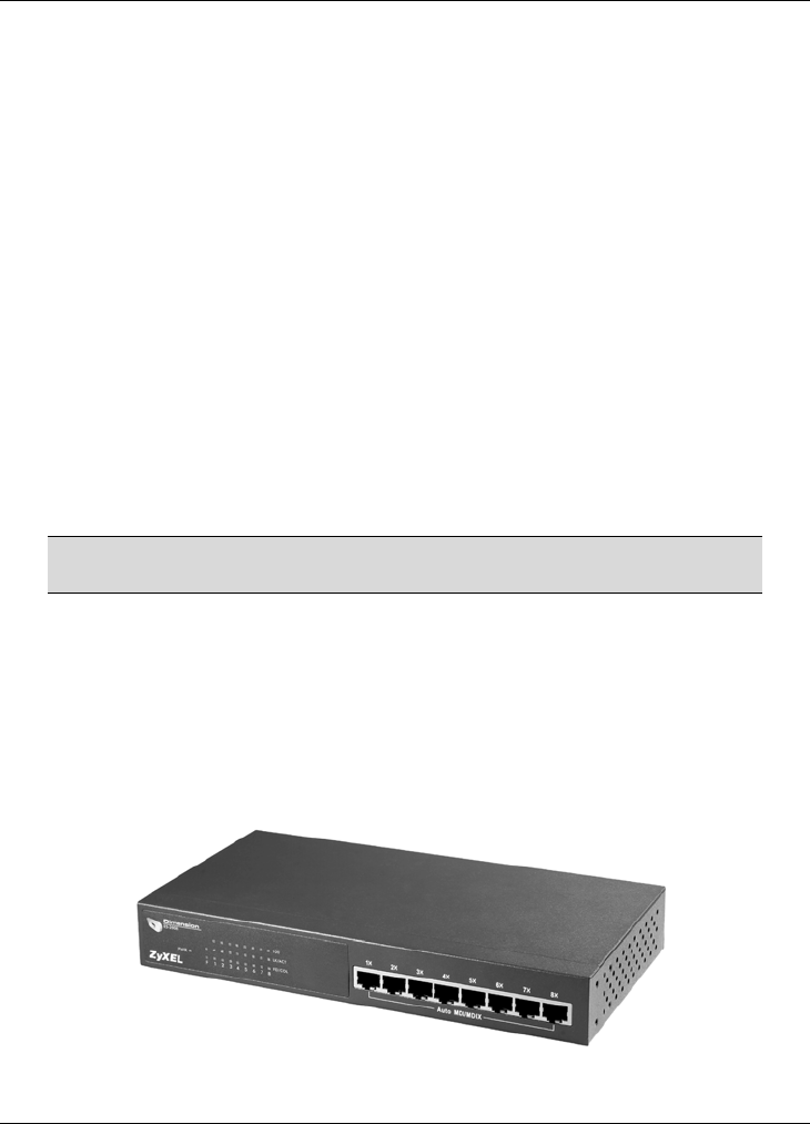
The front panel of the switch consists of eight auto-sensing, auto-negotiating 10/100Base-
TX Ethernet RJ-45 ports and/or one 100Base-FX fiber or gigabit port.
The LEDs are also located on the front panel of the switch.
Figure 2-1 ES-2008


