


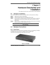

Dimension ES-2008 Ethernet Switch
2-4 Hardware Description and Installation
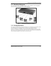
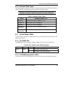
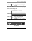
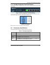
Figure 2-4 Ethernet Port LEDs
The following table describes the LEDs for the Ethernet ports on the front panel.
Table 2-3 Ethernet Port LED Descriptions
LED COLOR STATUS DESCRIPTION
On The port is operating at 100Mbps. 100 Green
Off No device is attached or the port is operating at
10Mbps.
On The port is connecting with a device.
Blinking The port is receiving or transmitting data.
LK/ACT Green
Off No device is attached.
On The port is operating in full-duplex mode.
Blinking Packet collisions are occurring
FD/COL Orange
Off No device is attached or the device is in half-
duplex mode.
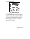
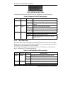
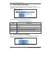
2.3.3 The Fiber Port
The 100FX fiber module is designed to extend the distance between the switch and other
Ethernet devices by up to 2 km using multi-mode fiber or 30 km using single-mode fibers.
The fiber port is not available on all switch models.
The LEDs provide real-time system status information of the fiber port. The following
table is a summary of LED status and meaning.
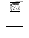
Table 2-4 100FX Module LED Descriptions
LED COLOR STATUS DESCRIPTION
On The fiber port is connected to an Ethernet device.
Blinking This fiber port is transmitting data.
LK/ACT Orange
Off No data is being transmitted.
On The port is operating in full-duplex mode. FD/COL Orange
Blinking Packet collision is occurring on this port.