


134 CHAPTER 6: USING RF PLANNING
Compute and
Place MAPs
When you perform Compute and Place for one or more coverage areas,
3WXM automatically calculates the number of MAP access points you
require and places them in appropriate locations on the floor. To do this,
two calculations are performed in 3WXM: One is based on capacity
(traffic engineering) and the other is based on pure RF coverage (at a
given data rate).
After the calculations are performed, the number of MAPs from capacity
and the number of MAPs from coverage are compared, and the bigger
count “wins.” If capacity wins, a grid pattern of MAPs is established. The
MAP coverage positions are reused, with the excess MAPs remaining in
their original grid position.
Using a “clean” RF model is imperative for best results. If you have many
parallel RF obstacles that are close together, the placement algorithm
tends to add more MAPs than are required. So, even with the automatic
clean layout mechanism in 3WXM, complex drawings demand additional
pruning and isolation of single RF obstacles objects to keep the RF
obstacle count as low as possible. For more information about cleaning
your floor plans, see “Clean Layout” on page 122.
When you are performing Compute and Place for a coverage area for the
first time, the results do not account for existing MAP access points.
Manual overrides of the MAP results are not taken into account if you
perform Compute and Place again.
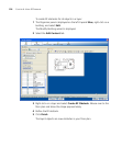
To determine the number and placement of MAPs:
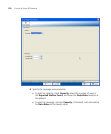
1 The Organizer panel is displayed on the left. Expand Sites, right-click on a
building, and select Edit.
The Modify Building wizard is displayed.
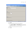
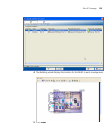
2 Select the Plan RF Coverage tab; then click Compute and Place MAPs.
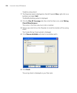
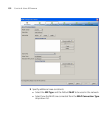
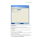
3 If required, under Wiring Closet, use the down arrow to select the
wiring closet associated with the area. Click Next.
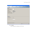
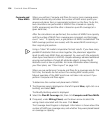
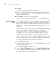
The Coverage Area Progress is displayed. Information is shown about the
number of MAPs per coverage area, and whether they were placed based
on coverage or capacity.