


SNC 5100
66 MAP for the SNC 5100
6-00020-02
Step 1. Inform the system administrator that it is necessary to replace the
Fibre Channel device connected to the SNC 5100 to resolve the
Fibre Channel errors.
Step 2. Repeat this MAP, beginning with the section “Verify Fibre Channel
Connections” on page 61, after replacing the external component.
MAP for the SNC 5100
Perform these steps if:
• RDY LED not blinking once per second after power has been on for one
minute
• The SNC 5100 is not responding
• SNC 5100 processor memory fault detected
• SNC 5100 PCI bus parity error detected
• SNC 5100 PCI interface error detected
• The ADIC Management Console Server could not verify the connection
to the SNC 5100
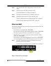
Observe Operational LED Behavior
When the SNC 5100 is first powered on, the front-panel’s LEDs flash a variety
of patterns as it performs the Power On Self Test (POST) and then starts
booting.
For more information, see “POST Error Codes” on page 197.
Within one minute, the SNC 5100 should have booted successfully and the
Ready LED should be blinking once per second.
If the Ready LED is not blinking as expected, go to “Start MAP” on page 42.
Temperature MAP
Perform these steps if:
• The SNC 5100 generates Trap Event Codes 62, 64, or 67 (Inlet Air, Outlet
Air, I/O Processor, or Fan have entered a Warning Range)