


4-74 Agilent 87130A Operating and Service Manual
Remote Operation
Example Speed Calculation
Example Speed Calculation
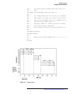
Switching speed is a function of pulse widths, sensing delays, the state of the
chosen channels, the sequence of relays driven and the power suply recovery
time. A sample program and timing diagram are provided to help the user
minimize switching time, since the user determines pulse widths, sensing
delays and which channels are opened or closed.
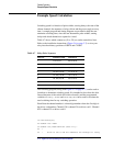
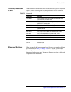
Table 4-7 shows which connectors (J1 to J31) are on the same drive lines.
Refer to the installation instructions (Figure 2-6 on page 2-7) to wire your
relay into the arbitrary positions of OPEN and CLOSE.
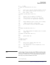
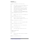
The following program, along with Figure 4-1 on page 4-77, can be used to
learn how to determine switching speed. It is intended to show how the drive
line architecture of the switch driver/driver board(s) and the programmed
variables of :
DELay,:WIDTh and TRIG:SEQ:DEL can be used to calculate the
total switching time for any switching operation.
Recall that the channel number is a three digit number where the first digit is
the driver card number. Channel 130 is channel 30 on driver card 1. Channel
825 is channel 25 on driver card 8.
10 DIM Closl$[40]
20 OUTPUT 709:”*RST”
30 OUTPUT 709;”ROUT:DRIV:ON (@100:111);”
40 !
50 ! Drive is set to ON for channels 100 through 111 using
Table 4-7 Relay Drive Sequence
Drive Line Connector Locator Channel List
1 J1, J2, J3, J4 00, 01, 02, 03
2 J5, J6, J7, J8 04, 05, 06, 07
3 J9, J10, J11, J12 08, 09, 10, 11
4 J13, J14, J15, J16 1 2, 13, 14, 15
5 J17, J18, J19, J20 16, 17, 18, 19
6 J21, J22, J23, J24 20, 21, 22, 23
7 J25, J26, J27, J28 24, 25, 26, 27
8 J29, J30, J31 28, 29, 30