


2-4 Agilent 87130A Operating and Service Manual
Installing the 87130A Attenuator/Switch Driver
Connecting Switch Drivers to Switches and Attenuators
Connecting Switch Drivers to Switches and
Attenuators
Driver Boards The standard 87130A attenuator/switch driver has a single internal driver
board capable of driving 31 switches. The attenuator/switch driver may also
be connected to a maximum of seven external 84940A driver board which
can control and sense switching states for up to 217 additional switches.
The internal driver card is terminated with a 68-pin SCSI II type connector
for connecting external switches. The 84941A distribution board should be
used to connect the switch driver to switches and attenuators.
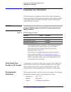
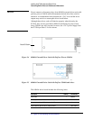
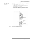
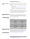
❍ The distribution board has 31 4-pin black output connectors
numbered J1 to J31 (silkscreened on the circuit side of the PCA), in
addition to 31 mating cables which allow a cable harness to be
quickly assembled to connect to relays. Refer to Figure 2-6 for pin
wiring that determines an OPEN or CLOSE condition on each
switch.
❍ Each relay (switch) is referred to as a channel by the switch driver.
Each channel has its own unique address. The switch driver begins
numbering channels at 0 instead of 1. Switch one, wired to J1 on
driver card 1, would have a channel address of 100.
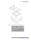
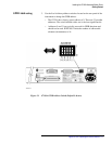
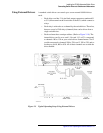
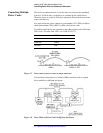
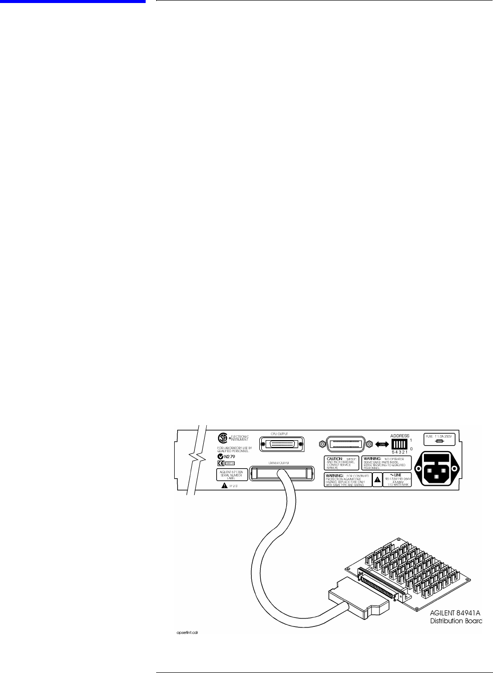
Using the Internal
Driver
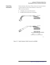
1. Connect the internal driver board of the switch driver which is
terminated with a 68-pin SCSI II type connector (driver output) to an
84941A distribution board. Use the six foot cable with two male 68-pin
SCSI II type connectors that is shipped with the 87130A.
Figure 2-2 Typical Operating Setup Using Internal Driver