Agilent 87130A Operating and Service Manual 4-9
Remote Operation
Programming the Switch Driver
Programming the Switch Driver
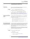
Initialization To make sure the bus and all appropriate interfaces are in a known state,
begin every program with an initialization statement.
Example CLEAR 709 ! initializes the interface of the driver.
Then initialize the switch driver to a preset state. For example:
OUTPUT 709;“*RST” ! initializes the instrument to a preset state.
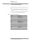
The actual commands and syntax for initializing the switch driver are
discussed in the section “Common Commands Reference” on page 4-12.
Refer to the controller manual for information on initializing the interface.
Setting Up the Switch
Driver
A typical switch driver setup would set the drive (ON or OFF) paths, delay
time, sensing (
ON or OFF), and pulse width. Some typical examples of the
commands sent to the driver are:
OUTPUT 709;“*CLS;ROUTE:DRIVE:ON (@100,102,104,106,....);”
OUTPUT 709;“ROUTE:DRIVE:OFF (@101,103,105,107,....);”
OUTPUT 709;“ROUTE:VERIFY:ON (@100,102,104,106,....);”
OUTPUT 709;“ROUTE:WIDTH .04,(@100,102,104,106,....);”
OUTPUT 709;“ROUTE:DELAY .03,(@100,102,104,106,....);”
Receiving Information
from the Switch Driver
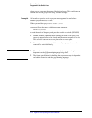
After receiving a query (command header followed by a question mark), the
switch driver interrogates the requested function and places the answer in its
output queue. The answer remains in the output queue until it is read or
another command is issued. When read, the message is transmitted across
the bus to the controller.
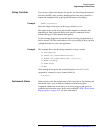
The input statement for receiving a response message from an instrument’s
output queue typically has two parameters; the device address and a format
specification for handling the response message.
Example To read the result of the query command
:GROUP:LABEL?
you would execute the statement:
10 OUTPUT 709;“ROUT:GROUP:LABEL? GROUP1”
20 ENTER 709;Setting$


