


Agilent 87130A Operating and Service Manual 4-75
Remote Operation
Example Speed Calculation
60 ! a range.
70 OUTPUT 709;”ROUT:DRIV:OFF (@112:130);”
80 !
90 ! Drive is set to OFF for remaining channels on driver
100 ! card 1.Unless channels are part of Drive list, no
110 ! pulse (:WIDTh) is sent.
120 OUTPUT 709;”ROUT:VER:ON (@100:111);”
130 !
140 ! Sensing is ON for channels 100 through 111.
150 ! VERify:ON works at switching time, and errors
160 ! (if they exists) are reported back immediately.
170 !
180 ! Unless channels are part of Verify list no sensing
190 (:DELay) can be valid. In other words,
190 ! you can choose to sacrifice sensing for speed.
200 !
210 !
220 OUTPUT 709;”ROUT:CLOS (@100:111);”
230 !
240 ! This command ensures all channels start in the same
250 ! (CLOSE) state.
260 OUTPUT 709;”ROUT:CLOS? (@100:111);”
270 !
280 ! Queries CLOSe list.
290 !
300 ENTER 709;Closl$
310 PRINT Closl$
320 !
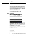
330 ! Switch driver response should look like:
1,1,1,1,1,1,1,1,1,1,1,1
340 ! This indicates all 12 active channels are in the
350 ! CLOSE) state.
360 PAUSE
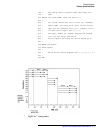
NOTE For this example, all relays start at the same (CLOSE) state and have delays
and pulse widths to make the calculation easier to follow. In real situations,
relays may be in different states. You must programmatically keep track of
these relays for your time calculations to be correct.
370 DIM Openl$[40]