


3-2 Agilent 87130A Operating and Service Manual
Specifications
Performance Specifications
Performance Specifications
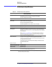
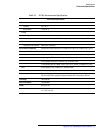
Table 3-1 87130A Electrical Specifications
1. Refer to “Compatible Switches and Attenuators” on page 1-4 if you are using switches or
attenuators made by another company.
Electrical Specifications
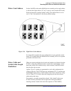
Drive Capacity - 87130A 248 relays, when mated with seven external 84940A daisy chained driver cards.
Each 84940A can drive up to 31 relays. The equivalent of one 84940A
driver card is installed within the 87130A.
Voltage + 24 + 3.0 / − 1.5 Vdc
Current Pulses 1600 mA maximum per four relay group
400 mA per relay (typically 500 mA maximum)
Pulse width is adjustable for 5 ms to 1275 ms
± 5 ms, in 5 ms steps.
Load Inductance
1
Typically < 500 mH
Load Capacitance Typically < 0.01
µF
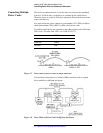
Switching Speed Sensing delay is adjustable, per relay, from 5 to 1275 ms
± 5 ms. Pulse width is also
adjustable, per relay, from 5 to 1275
± 5 ms. Power Supply RecoveryTime is adjustable
from 0 to 200 msec
Refer to Chapter 6, “Troubleshooting.” The final switching speed is a function of
pulse widths, sensing delays, the sequence of relays driven, the state of the chosen
channels, and the Power Supply Recovery Time.
Remote Programming All functions are GPIB programmable except the line switch and bus address.
All functions are programmable to conform with IEEE 488.2-1987 Standard Commands
for Programmable Instruments (SCPI).
The 87130A can output over the interface almost all settings, error/malfunction codes
and operational status codes.
Interface to Controller GPIB
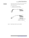
Interface to External Driver Cards 36-pin SCSI II type
Interface to Relays 68-pin SCSI II type
Hardware Limits Each open collector driver IC can drive only one channel (a maximum of four switches) at
a time to avoid exceeding package dissipation limits.