


5-8 Agilent 87130A Operating and Service Manual
Replaceable Parts
1 Required for 220V options
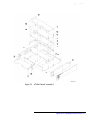
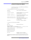
Table 5-4 Replaceable Parts - 87130A Cable Assembly
Part Location Part Number Quantity Description Reference Designator
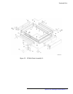
1 87130-62065 1 Driver board A2
2 87130-60002 1 Controller board A1
3 0950-2252 1 Power supply 110 W A3
4 87130-60001 1 Display board A4
5 87130-60008 1 GPIB address board A5
3101-2325 1 GPIB address switch (part of GPIB address board)
—
6 87130-60007 1 AC line cable assembly —
2110-0782 1 Fuse T 1A 250V UL/CSA (part of AC input module) —
2110-0674
1
1 European fuse T 1A 250V IEC (part of AC input module) —
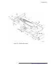
7 87130-60006 1 34/36-pin SCSI cable —
8 87130-60005 1 GPIB address cable W2
9 87130-60004 1 24-pin GPIB cable W1
10 87130-60003 1 Display cable W3
11 3101-3008 1 Rocker switch
—
12 0515-1946 2 FH screw M 3.0 x 0.5 x 6 torx —
13 1252-1900 2 Screw, jack 4-40 —
14 2260-0009 Nut, hex 4-40 —
15 0515-0430 Torx pan M 3.0 x 0.6 x 6 —
16 0515-2028 4 FH screw M 2.5 —
19 0515-0431 2 Torx pan M 3.5 x 0.6 x 6 —
U7 70611-80017 1 EPROM —
U8 70611-80018 1 EPROM —
20 2110-0003 1 Fuse 3A 250 V F —
21 2110-0003 1 Fuse 3A 250V F —
22 0515-1860 6 FH screw M 3.5 x 0.6 x 10 torx —