


Agilent 87130A Operating and Service Manual 2-11
Installing the 87130A Attenuator/Switch Driver
Connecting Switch Drivers to Switches and Attenuators
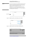
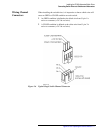
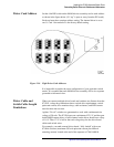
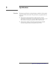
Driver Card Address Set the 4-bit DIP switch on the 84940A driver assembly card to each address
as shown in the figure below. (S1 “up” is open or away from the PC board.)
Each card must have a unique address setting. The internal driver is set to
card 1. Card 1 shown below is the factory default setting.
Figure 2-10 Eight Driver Card Addresses
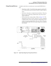
It is impossible to predict the exact configuration of your particular switch
matrix. It is assumed that each 84940A driver assembly will be in a separate
grounded switch matrix box.
Driver Cable and
Switch Cable Length
Limitations
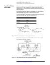
When you connect multiple driver boards and switches at a distance from the
87130A, voltage drop limitations due to switch drive requirements, switch
quiescent current, drive transistor drop, cable resistance, and LED current
must be taken into account.
Agilent “24 volt” switches are guaranteed to work with a minimum drive
voltage of 20 volts. The 87130A puts out a minimum of 22.5 V, and the open
drain DMOS output drivers of each channel on the driver board have a drop
of 1.0 V. Thus 1.5 V is left for the total voltage drop for the driver board
cables and switch wires.
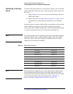
For example, a seventh external driver board, “fully loaded” with seven
87104A switches (maximum 350 mA quiescent current plus 400 mA
actuating current) located at the end of the sequence of 70611-60010,