Agilent 87130A Operating and Service Manual 1-3
Introducing the 87130A Attenuator/Switch Driver
Features of the Attenuator/Switch Driver
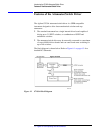
Drive Pulse and
Sensing
The attenuator/switch driver can deliver 500 mA, 24 Vdc current pulses to
31 individual switch sections and up to a total of 248 switch sections by the
addition of external 84940A driver boards (or driver boards inside externally
connected equipment such as switch matrixes). These low impedance pulses
can be adjusted for pulse width in order to optimize switching speed. Pulse
width and sensing delay can be set from 0.005 to 1.275 seconds.
Sensing Disabled
Each switch coil is internally connected to the + 24 V bias supply. A power
transistor on the driver board supplies the ground that will activate the switch
coil. The controller assembly actuates the transistor for a predetermined time
that is set by the :WIDTh command. (Refer to “:WIDTh” on page 4-67.) The
default setting is 30 ms.
Sensing Enabled
For switches that can be sensed, the switch coil is internally connected to the
+ 24 V bias supply via a dc switch that removes the bias from the activated
coil after the switch has changed position and applies the bias to the opposite
coil. By monitoring the presence of this bias through the opposite coil, the
switch controller can determine the switch position.
After the initial 30 ms closure pulse, an additional 20 ms time is allowed for
the sense lines to settle. At this time an error and a programmed position
check are performed.
The power supply allows the switch driver four switching operations at the
same time. This means that at the default setting, seven groups of four
switches and one group of three switches will each take 50 ms to switch and
verify. This results in a default switching speed of 0.4 seconds for 31 relays
with sensing enabled. Refer to “Example Speed Calculation” on page 4-74
for more information.


