


2-10 Agilent 87130A Operating and Service Manual
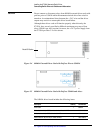
Installing the 87130A Attenuator/Switch Driver
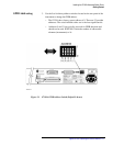
Connecting Switch Drivers to Switches and Attenuators
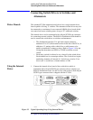
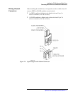
Optimizing Switching
Speed
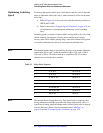
To increase the speed at which your switch matrix operates, refer to the table
below to determine which four relays, when connected, will be on the same
drive lines.
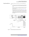
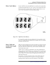
a. Refer to Figure 2-6 to wire your relays into the arbitrary positions of
OPEN and CLOSE.
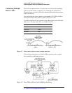
b. Refer to the section “Example Speed Calculation” on page 4-74 for
an explanation on calculating and minimizing overall switching
time.
Switching speed is a function of pulse widths, sensing delays, the state of the
chosen channels, the sequence of relays driven and the power supply
recovery time. Pulse widths, sensing delays, and which channels are opened
or closed are determined by the user, and cannot be predicted here.
NOTE The channel number must be preceded by the driver card number. Channels
connected to driver card 1 would be numbered 100 to 130; card 2, 200 to
230; card 3, 300 to 330, and so forth up to card 800 to 830. All of these
channels are set with the drive enabled.
.
NOTE The maxium Power Supply Recovery Time should only be required when
driving multiple external driver boards with longer interconnect cables. A
significant switching speed advantage can be realized if this value is reduced
from the 200 msec default. See the command called “TRIGger” on
page 4-62 and the “Example Speed Calculation” on page 4-74.
Table 2-1 Relay Drive Sequence
Drive Line Connector Locator Channel List
1 J1, J2, J3, J4 00, 01, 02, 03
2 J5, J6, J7, J8 04, 05, 06, 07
3 J9, J10, J11, J12 08, 09, 10, 11
4 J13, J14, J15, J16 12, 13, 14, 15
5 J17, J18, J19, J20 16, 17, 18, 19
6 J21, J22, J23, J24 20, 21, 22, 23
7 J25, J26, J27, J28 24, 25, 26, 27
8 J29, J30, J31 28, 29, 30