2-2 Agilent 87130A Operating and Service Manual
Installing the 87130A Attenuator/Switch Driver
Getting Started
Getting Started
Initial Inspection 1. Unpack and inspect the shipping container and its contents thoroughly to
ensure that nothing was damaged during shipment. If the shipping
container or cushioning material is damaged, the contents should be
checked both mechanically and electrically. A procedure for checking
the electrical performance is given in Chapter 4, Verification.
❍ If the shipping container is damaged, or the cushioning material
shows signs of stress, notify the carrier as well as Agilent
Technologies. Keep the shipping material for the carrier’s
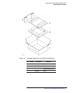
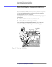
inspection. Refer to Figure 1-3.
❍ If the contents are damaged or defective, contact your nearest
Service Center listed under “Service and Support” on page v.
Agilent will arrange for repair or replacement of the damaged or
defective equipment.
Preparing for Use 2. Use the following properties of the attenuator/switch driver to plan your
system configuration.
Power requirements
The internal power supply adjusts automatically to the input line voltage.
See table 3-2 on page 3-3 for additional information.
Power cord
In accordance with international safety standards, a three-wire power cable
is provided with this instrument. When it is connected to an appropriate ac
power receptacle, this cable grounds the instrument cabinet. The type of
power cable plug shipped with each instrument depends on the country of
destination.
Fuses
The 87130A is shipped with a 3A fuse (F3) installed in the + 24 Vdc line and
a 3A fuse (F2) in the + 5 Vdc line. The 1 A, 250 V power line fuse is located
inside the AC input module.


