


Agilent 87130A Operating and Service Manual 2-5
Installing the 87130A Attenuator/Switch Driver
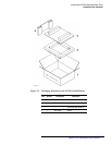
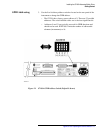
Connecting Switch Drivers to Switches and Attenuators
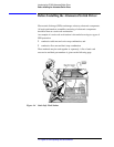
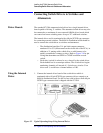
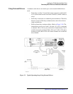
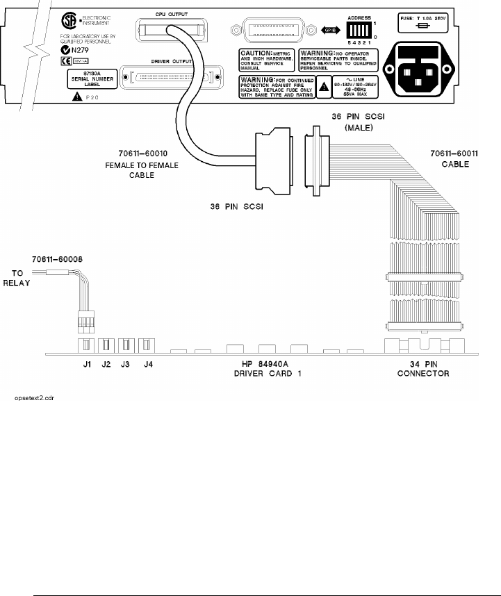
Using External Drivers A standard switch driver can control up to seven external 84940A driver
cards.
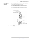
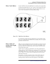
❍ Each driver card has 31 4-pin black output connectors numbered J1
to J31 (silkscreened on the circuit side of the PCA) which connect to
relays.
❍ Each relay is referred to as a channel by the switch driver. Therefore,
there are a total of 248 relays (channels) that can be driven from a
single switch driver.
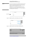
❍ Each card must have a unique address. (Refer to Figure 2-10). The
internal driver card is set to card 1. On card 1, J1 to J31 correspond
to channels 100 to 130 on your switch driver channel menu. Card 2
would correspond to channels 200 to 230; card 3, 300 to 330, and so
forth up to card 8, 800 to 830. All of these channels are set with the
drive enabled.
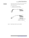
Figure 2-3 Typical Operating Setup Using External Drivers