


Chapter 18: Configuring Router Redundancy
Router redundancy protocols use a virtual IP address to support a primary router
and multiple backup routers. The backup routers can be configured to take over the
workload if the master router fails, or can also be configured to share the traffic load.
The primary goal of router redundancy is to allow a host device which has been
configured with a fixed gateway to maintain network connectivity in case the primary
gateway goes down.
This switch supports the Virtual Router Redundancy Protocol (VRRP). VRRP allows
you to specify the interface of one of the routers participating in the virtual group as
the address for the master virtual router, or to configure an arbitrary address for the
virtual master router. VRRP then selects the backup routers based on the specified
virtual router priority.
Router redundancy can be set up in any of the following configurations. These
examples use the address of one of the participating routers as the master router.
When the virtual router IP address is not a real address, the master router is
selected based on priority. When the priority is the same on several competing
routers, then the router with the highest IP address is selected as the master.
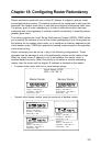
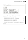
• A master virtual router with one or more backup routers.
Virtual Router (VR23)
VRIP = 192.168.1.3
Master Router
VRID 23
IP(R1) = 192.168.1.3
IP(VR23) = 192.168.1.3
VR Priority = 255
Backup Router
VRID 23
IP(R2) = 192.168.1.5
VRIP(VR23) = 192.168.1.3
VR Priority = 100
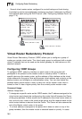
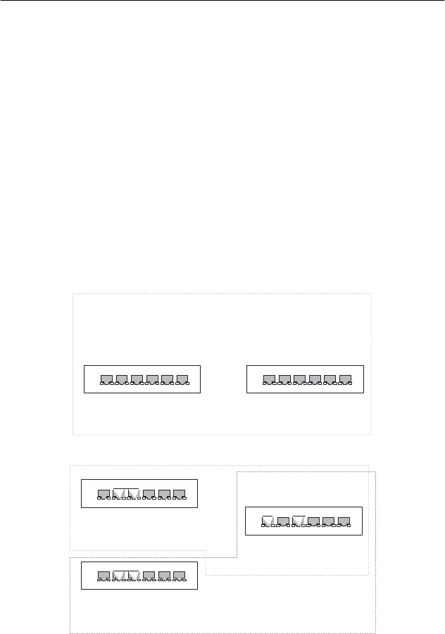
• Several virtual master routers using the same set of backup routers.
Master Router
VRID 23
IP(R1) = 192.168.1.3
IP(VR23) = 192.168.1.3
VR Priority = 255
Master Router
VRID 25
IP(R2) = 192.168.2.17
IP(VR25) = 192.168.2.17
VR Priority = 255
Backup Route
r
VRID 23
IP(R3) = 192.168.1.4
IP(VR23) = 192.168.1.3
VR Priority = 100
VRID 25
IP(R3) = 192.168.2.18
IP(VR23) = 192.168.2.17
VR Priority = 100
18-1