


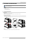
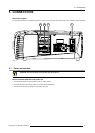
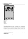

5. Connections
5.3 Communication connections
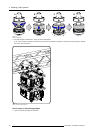
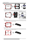
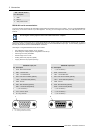
Communication interface
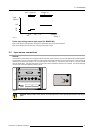
1 2
3
RS232 / 422 OUT
RS232 / 422 INUSB
DIAGNOSTIC CODE IR RECEIVER
STBY / ON
OK
REC
WARNING IR
10/100 ACT
10/100
BASE-T
IN
OUT
DMX
REMOTE
CTRL
A
B
C
D
E
F
G
H
I
J
K
L
M
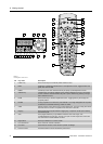
Image 5-10
Communication connections
A Projector status LED
B Warning LED
C IR signal acknowledged LED
D IR signal received LED
E Ethernet port
F DMX in port
G DMX out port
H USB port
I RS232/422 output port
J RS232/422 input port
K XLR input port for remo
te control
L IR receiver
M Two digit 7-segment
display for diagnostic code
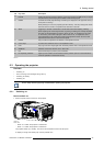
Projector status
The projector “status” LED (A) lights up green while in operation. The same LED lights up red when the projector is switched to
standby.
Besides the projector status LED (A) the communication interface has also a “warning” LED (B) which blinks in case the projector
encounters an internal problem concerning fan speed, temperature, supply voltages, ... etc. These type of problems still allows
the projector to operate (the show can go on) but an action will be required within a short time period. More information about the
involved problem is given on the local LCD display of the projector.
A two character 7-segment display (M) shows, during normal operation, the selected input slot number. If an error has occurred
then an error code appears on this two digit display.
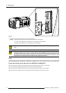
IR communication (RC5)
An IR receiver (L) is mounted on the communication interface. Note that there is also an IR receiver mounted at the front and at the
back of the projector. When using the remote control unit (wired or wireless), the “IR REC” (D) and the “IR OK” (C) LED’s will light
up indica
ting an IR signal was received and recognized.
Wired rem
ote control
If desired the remote control unit can be wired and plugged in into the male XLR port (K) on the communication interface.
R59770057 CLM HD8 15/03/2010
39