


164 Brocade MLX Series and Brocade NetIron XMR Hardware Installation Guide53-1002373-02
Installing a Brocade MLX-8 router
3
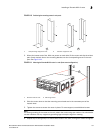
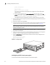
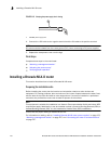
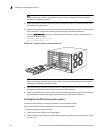
FIGURE 116 Crimping the power supply wire in the lug
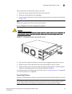
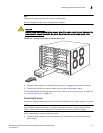
4. Connect the -48V cable to the negative terminal and the 0V cable to the positive terminal.
NOTE
DC return must be isolated from the router ground (DC-I) when connecting to DC power supplies.
5. Replace the transparent cover over the lugs.
Final steps
Complete these steps in the order listed:
• “Attaching a management station”
• “Activating the power source”
• “Verifying proper operation”
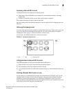
Installing a Brocade MLX-8 router
This section describes how to install a Brocade MLX-8 router.
Preparing the installation site
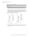
Before installing the router, plan the location and orientation relative to other devices and
equipment. For cooling purposes, allow a minimum of six inches of space between the sides, front,
and the back of the router and walls or other obstructions. If a router is installed in a perforated
enclosure, the perforations must cover at least 60 percent of the surface.
NOTE
This equipment is suitable for installation in a Network Telecommunication facility and where NEC
requirements apply. Additionally, it may be installed in either a Common Bonding Network (CBN) or
Isolated Bonding Network (IBN). It is not intended for Outside Plant (OSP) installations.
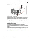
Ensure that the proper cabling is installed at the site.
For information on cabling, refer to “Installing Brocade MLX-8 router power supplies” on page 170,
“Attaching a management station” on page 227, and “Connecting the router to a network device”
on page 317.
1 #8 AWG power supply wire
1