


28 Brocade MLX Series and Brocade NetIron XMR Hardware Installation Guide
53-1002373-02
Router modules
1
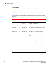
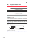
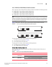
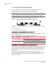
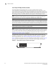
8x10GE-X interface module LEDs
The 8x10GE-X interface module LEDs indicate module and port status, as described in Table 7.
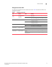
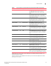
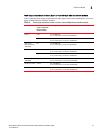
Power supply requirements for 8x10GE-X modules
Table 8 lists the power supply requirements for each type of router when installing 8x10GE-X
modules.
TABLE 7 8x10GE-X module LEDs
LED Location State Meaning
Power Lower left corner of module Green Module is receiving power
Off Module is not receiving power
Link/Act Below the ports. Top port
LED on left, bottom port LED
on right.
Green
blinking
Port enabled and link is passing traffic. LED is solid
green when link is idle.
Off Port is disabled.
TABLE 8 Power supply requirements for 8x10GE-X modules
Router type Number of 8x10GE-X
modules installed
Power supply requirements
MLXe-4 one one 1200W PSU
for 1+1 redundancy, install two 1200W PSU
two to four two 1200W PSU
for 2+2 redundancy, install four 1200W PSU
one 1800W PSU
for 1+1 redundancy, install two 1800W PSU
MLX-4 and
Brocade NetIron
XMR 4000
four one 1200W PSU
for 1+1 redundancy, install two 1200W PSU
MLXe-8 and
Brocade NetIron
XMR 8000
seven two 1200W PSU
for 2+2 redundancy, install four 1200W PSU
eight three 1200W PSU
for 3+1 redundancy, install four 1200W PSU
two 1800W PSU
for 2+3 redundancy, install four 1800W PSU
All 16-slot routers fifteen four 1200W PSU
for 4+4 redundancy, install eight 1200W PSU
sixteen five 1200W PSU
for 5+3 redundancy, install eight 1200W PSU
four 1800W PSU
for 4+4 redundancy, install eight 1800W PSU
All 32-slot routers twenty-eight four 2400W PSU
for 4+4 redundancy, install eight 2400W PSU
twenty-nine to
thirty-two
five 2400W PSU
for 4+4 redundancy, install eight 2400W PSU
four 3000W PSU
for 4+4 redundancy, install 3000W PSU