


374 Brocade MLX Series and Brocade NetIron XMR Hardware Installation Guide
53-1002373-02
Replacing fan assemblies
8
DANGER
For safety reasons, the ESD wrist strap should contain a 1 megohm series resistor.
Removing a fan assembly from the chassis
To remove a fan assembly from the chassis that is receiving power, complete the following steps:
1. Put on the ESD wrist strap and ground yourself by inserting the plug into the ESD connector on
the router.
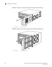
2. Depending on your router model (Brocade MLX-32 or Brocade MLXe-32) use the appropriate
screwdriver to remove the screws that secure the fan assembly faceplate to the rear of the
router.
DANGER
The 32-slot router fan assembly is heavy and will be off-balance as you remove it. Use both
hands on the handle.
DANGER
Be careful not to insert your fingers into the fan while removing it from the device. The fan blades
may still be spinning at a high speed.
CAUTION
Removing the rear fan modules on a 32-slot router provides access to bus bars and the
backplane. Avoid contact with these parts. Hazardous energy levels exist at these locations.
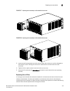
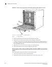
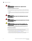
3. Remove the fan assembly by grasping the handle on the faceplate and pulling the fan
assembly toward you. Pulling the fan assembly unseats the fan connector from the router.
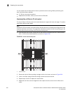
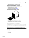
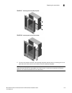
Attaching the upward deflector
The upward deflector is placed between the fan assembly handle and the fan assembly faceplate.
To install the upward deflector to each fan assembly, complete the following steps:
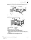
1. Using a Phillips screwdriver, detach the fan assembly faceplate by removing the three screws
from each side of the fan assembly. Refer to Figure 237 on page 367.
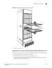
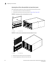
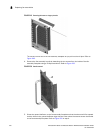
2. If present, remove and discard the tape that stabilizes louvers in some fan assembly models.
When present, the tape is located on the right and left sides of the fan assembly.