


210 Brocade MLX Series and Brocade NetIron XMR Hardware Installation Guide53-1002373-02
Installing a Brocade MLX-32 router
3
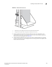
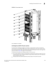
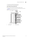
• During the initial installation of modules, it is recommended that you insert all the modules
into the appropriate router slots before tightening the module screws.
For instructions about installing 100xGbE interface modules, refer to “Installing 2x100GbE
interface modules in Brocade MLX routers” on page 151.
For information about how to disable and re-enable power to interface modules, see “Disabling and
re-enabling power to interface modules” on page 321
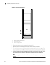
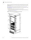
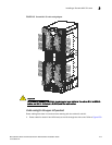
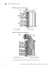
When populating the Brocade MLX-32 router, the modules must be installed in the appropriate
slots:
• Management modules - management slots 1 and 2
• Switch fabric modules - switch fabric slots 1-8
• Interface modules - interface slots 1-32
Figure 12 on page 16 shows the locations of these slots.
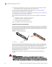
Using the insertion and extraction tool
Due to the high density of cables that the Brocade MLX-32 router can support, it may be difficult to
insert and remove the RJ45 and optical connectors, especially when replacing an existing module.
An insertion and extraction tool has been provided in the Brocade MLX-32 accessory kit to make
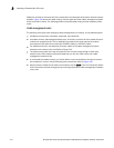
this task easier. Refer to Figure 147.
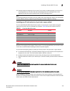
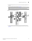
FIGURE 147 insertion and extraction tool
Use the tool to grasp the plug of the modular connector at its narrow end (the end closest to the
attached cable), and insert the connector into the proper interface module. Grasping the plug at
the wide end during insertion may result in the tool being difficult to release and remove.
When using the tool to extract the plug of a modular connector, cover the entire length of the plug
with the tool. Notice that one end of the tool has a “hook” side. Use this side to compress the
locking tab while you remove the connector.
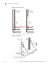
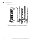
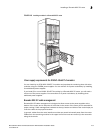
The Brocade MLX-32 ships with empty module slots, and upper and lower shipping panels
installed.
DANGER
The intra-building ports of the equipment or subassembly is suitable for connection to
intra-building or unexposed wiring or cabling only. The intra-building ports of the equipment or
subassembly MUST NOT be metallically connected to interfaces that connect to the outside plant
(OSP) or its wiring. These interfaces are designed for use as intra-building interfaces only (Type 2
1 Hooked tab 2 Stepped tab
1
2