


Brocade MLX Series and Brocade NetIron XMR Hardware Installation Guide 221
53-1002373-02
Installing a Brocade MLX-32 router
3
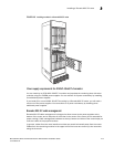
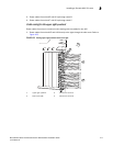
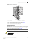
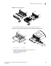
FIGURE 157 Routing lower-right quadrant cables
2. Route cables from slots #30 and #29 down through comb A. Refer to Figure 157.
3. Route cables from slots #28 and #27 down through comb B.
4. Route cables from slots #26 and #25 down through comb C.
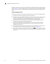
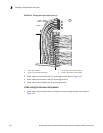
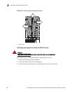
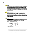
Accessing modules for service
With the cables bundled correctly, it is easier to access the modules for service. Gently move the
cable bundles to the side to access a module. Use the appropriate Phillips or flat-blade screwdriver
with an extended shaft to disconnect the cables from the module and remove the module. There is
no need to undo the cable cinches or cable ties. Refer to Figure 158.
NOTE
This procedure is easier with two people. One person can hold the cable bundles aside while the
other person loosens the connectors and removes the module.
CAUTION
Be careful not to overtighten or cross-thread cable connector screws.
1 Lower right quadrant 3 Comb B (slots #27 and #28 cables)
2 Comb A (slots #29 and #30 cables) 4 Comb C (slots #25 and #26 cables)
2
3
4
1