


Brocade MLX Series and Brocade NetIron XMR Hardware Installation Guide 325
53-1002373-02
Managing the device
7
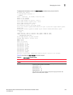
To display this information, enter the show chassis command at any level of the CLI.
Brocade# show chassis
*** Brocade MLX-4 chassis ***
---POWERS ---
Power 1 (32011000 - AC 1200W): Installed (OK)
Power 2: not present
Power 3: not present
Total power budget for device = 1200 W
Total power used by system core = 183 W
Total power used by LPs = 386 W
Total power available = 631 W
Slot Power-On Priority and Power Usage:
Slot1 pri=1 module type=NI-MLX-1Gx20-GC 20-port 10/100/1000 Copper Module power
usage=156W
Slot4 pri=1 module type=NI-X-OC48x8 8-port OC48/12 STM16/STM4 Module power
usage=230W
--- FANS ---
right fan tray (fan 1): Status = OK, Speed = MED-HI (90%)
right fan tray (fan 2): Status = OK, Speed = MED-HI (90%)
--- TEMPERATURE READINGS ---
Active Mgmt Module: 36.500C 49.625C
Standby Mgmt Module: 36.250C 51.0C
SNM1: 37.0C
SNM2: 38.0C
SNM3: not present
LP1 Sensor1: 41.5C
LP1 Sensor2: 50.625C
LP4 Sensor1: 39.0C
LP4 Sensor2: 49.250C
LP4 Sensor3: UNUSED
LP4 Sensor4: 38.5C
LP4 Sensor5: 47.750C
LP4 Sensor6: UNUSED
Fans are in auto mode. Temperature Monitoring Poll Period is 60 seconds
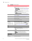
Table 46 describes the show chassis command output.
TABLE 46 show chassis command output
Field Description
Powers
Power <num>, <part num> The Power <num> is the power supply number as positioned in the device. The
number of power supplies are as follows:
4-slot devices: 1 – 3
8-slot devices: 1 – 4
16-slot devices: 1 – 8
32-slot devices: 1 – 8
The <part num> is the part number of the power supply purchased. This
applies to AC and DC power supplies.