


190 Brocade MLX Series and Brocade NetIron XMR Hardware Installation Guide53-1002373-02
Installing a Brocade MLX-32 router
3
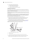
4. Connect the -48V cable to the negative terminal and the 0V cable to the positive terminal on
the power supply.
NOTE
DC return must be isolated from the router ground (DC-I) when connecting to the power supply.
5. Replace the transparent cover.
This equipment installation must meet NEC/CEC code requirements. Consult local authorities for
regulations.
Final steps
Complete these steps in the order listed:
• “Attaching a management station”
• “Activating the power source”
• “Verifying proper operation”
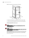
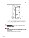
Installing a Brocade MLX-32 router
The Brocade MLX-32 router can be installed on a 2-post Telco open frame rack or a 4-post
enclosed rack or cabinet.
Preparing the installation site
Before installing the router, plan the location and orientation relative to other devices and
equipment. For cooling purposes, allow a minimum of six inches of space between the sides, front,
and the back of the router and walls or other obstructions. If a router is installed within a perforated
enclosure, the perforations must cover at least 60 percent of the surface.
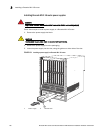
You will need to use a mechanical lift to move and install the router. Be sure to allow enough
working room for the lift.
NOTE
Make sure your site provides 200-240 AC power.
Ensure that the proper power and network cabling is installed at the site.
For information on cabling, refer to “Brocade MLX-32 cable management” on page 213, “Installing
power supplies in a Brocade MLX-32 router” on page 222, “Attaching a management station” on
page 227, and “Connecting the router to a network device” on page 317.
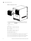
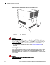
Unpacking a Brocade MLX-32 router
The Brocade MLX-32 router ships with the following items:
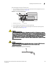
1AWG power supply wire:
#8 AWG wire for 1200W power supply
#6 AWG wire for 1800W power supply