


244 Brocade MLX Series and NetIron XMR Hardware Installation Guide
53-1002373-02
Installing a Brocade NetIron XMR 4000 router
4
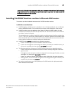
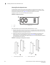
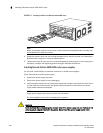
Removing the extra shipment screws
The Brocade MLX- ships with two extra screws installed in the right side of the chassis. These
screws secure the fan tray, protecting it from damage during shipment. You must remove these
screws before installing the router. Figure 168 shows the location of the screws.
To perform this task, you need a #2 Phillips-head screwdriver.
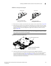
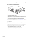
FIGURE 168 Shipping screw locations
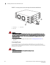
Follow these steps to mount a Brocade NetIron XMR 4000 router in a rack.
1. Determine the position of each router in the rack. For example, place routers with the fewest
modules near the top of the rack, routers with more modules near the middle of the rack, and
fully populated routers near the bottom of the rack.
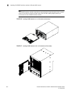
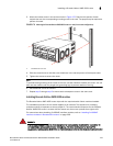
2. Position two of the four mounting screws for each router according to the spacings of the
keyhole slots on the mounting brackets, as shown in Figure 169. When tightening the
mounting screws in the rack post, leave approximately 1/4 inch clearance between the back of
the screw head and the rack post.
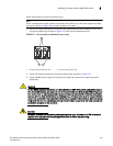
FIGURE 169 Positioning the mounting screws in rack posts
1 Front 3 Shipping screws
2Rear
1 Unequal flange equipment rack 2 Network equipment rack
3
1
2
5"
3"
1 2