


364 Brocade MLX Series and Brocade NetIron XMR Hardware Installation Guide
53-1002373-02
Replacing fan assemblies
8
4. Insert the new fan assembly into the slot and push the assembly in until the faceplate is flush
with the device. Pushing the assembly in seats the fan connector with the device connector.
5. Secure the fan assembly to the device by tightening the four captive screws.
6. Access the CLI, and enter the show chassis command to verify that both fans are operating
normally.
Front fan assembly replacement steps
Perform the following steps to replace a fan assembly.
1. Put on the ESD wrist strap and ground yourself by inserting the plug into the ESD connector
located on the front of the router.
2. Using the flat-blade screwdriver, loosen the four captive screws that secure the fan assembly
to the front of the router.
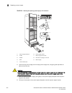
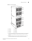
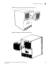
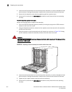
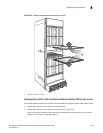
3. Grasp the handle on the fan assembly and pull it toward you as shown in Figure 234. Pulling
the fan assembly unseats the assembly connector from the router connector.
DANGER
Be careful not to accidently insert your fingers into the fan while removing it. The fan may still be
spinning at a high speed.
FIGURE 234 Replacing a front fan assembly from an MLX or XMR 16-slot router
4. Insert the new fan assembly into the slot and push the assembly in until the faceplate is flush
with the device. Pushing the assembly in seats the fan connector with the device connector.
5. Tighten the four captive screws to secure the fan to the device.
6. Access the CLI, and enter the show chassis command to verify that the fans are operating
normally.