


Brocade MLX Series and Brocade NetIron XMR Hardware Installation Guide 265
53-1002373-02
Installing a Brocade NetIron XMR 16000 router
4
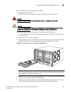
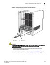
5. Tighten the screws to secure the router.
NOTE
For better grounding of the router to the rack, attach the router using star washers. You can also use
star washers with single-hole grounding lugs to prevent rotation of the lug.
6. Repeat step 2 through step 5 to mount each router in the rack.
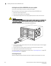
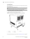
Installing Brocade NetIron XMR 16000 modules
The Brocade NetIron XMR 16000 router ships with the required switch fabric modules installed.
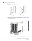
The procedure in this section applies to all modules. The sequence for installing multiple modules
is important to ensure proper fit. For the Brocade NetIron XMR 16000 router, start with the lowest
row, and move upwards, installing modules from left to right.
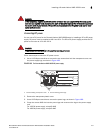
For instructions about installing 2x100GbE interface modules, refer to “Installing 2x100GbE
interface modules in Brocade MLX routers” on page 239.
DANGER
The intra-building port or ports of the equipment or subassembly is suitable for connection to
intra-building or unexposed wiring or cabling only. The intra-building port or ports of the
equipment or subassembly MUST NOT be metallically connected to interfaces that connect to the
outside plant (OSP) or its wiring. These interfaces are designed for use as intra-building
interfaces only (Type 2 or Type 4 ports as described in GR-1089-CORE, Issue 5) and require
isolation from the exposed OSP cabling. The addition of Primary Protectors is not sufficient
protection in order to connect these interfaces metallically to OSP wiring.
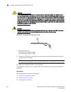
NOTE
Brocade NetIron XMR modules are dedicated, which means that you must install them in Brocade
NetIron XMR routers only. For example, if you install a Brocade NetIron XMR module in another
Brocade router or install a module intended for another Brocade router in the Brocade NetIron XMR
router, the router and module will not function properly.
Although management modules are designed to be hot-swappable, you must upgrade the software
on all interface modules and management modules to the appropriate software release before
installing them. For more information on the appropriate software release, refer to the Hardware
Installation Notes that shipped with the management module.
For information about how to disable and re-enable power to interface modules, see “Disabling and
re-enabling power to interface modules” on page 321
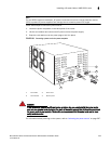
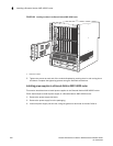
Table 42 identifies the slots where you install modules. Identification markings are located at the
base of each slot.
TABLE 42 Brocade NetIron XMR 16000 module installation
Module Slot number
Management modules Active module – M1 (upper).
Redundant module – M2 (lower).