


218 Brocade MLX Series and Brocade NetIron XMR Hardware Installation Guide53-1002373-02
Installing a Brocade MLX-32 router
3
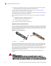
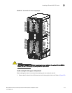
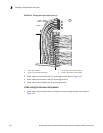
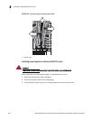
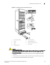
FIGURE 153 Routing upper-right quadrant cables up
2. Route cables from slots #13 and #14 up through comb A. Refer to Figure 153.
3. Route cables from slots #11 and #12 up through comb B.
4. Route cables from slots #9 and #10 up through comb C.
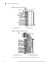
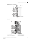
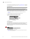
Cable routing for the lower-left quadrant
1. Route cables from slots #18 and #17 directly to the left through the side comb. Refer to
Figure 154.
1 Upper right quadrant 3 Comb B (slot #11 and #12 cables)
2 Comb C (slot #9 and #10 cables) 4 Comb A (slot #13 and #14 cables)
1
2
3
4