


Brocade MLX Series and Brocade NetIron XMR Hardware Installation Guide 21
53-1002373-02
Router modules
1
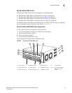
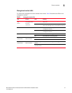
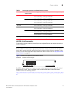
Management module LEDs
The LEDs on all management module models are the same. Table 2 describes the LEDs on the
management module.
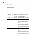
TABLE 2 Management module LEDs
LED Position State Meaning
Port 1
and
Port 2
Each adjacent to
the auxiliary flash
slot that it
represents
On or blinking The software is currently accessing the auxiliary
flash card.
Off The software is not currently accessing a auxiliary
flash card, although there is one inserted in the slot.
Active Lower Left On The module is functioning as the active
management module.
Off The module is functioning as the redundant
management module.
Pwr Upper Left On The module is receiving power.
Off The module is not receiving power.
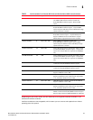
10/100/1000
Ethernet Port
Above and right of
RJ45 connector
On (Green) A link is established with the remote port.
Off No link is established with the remote port.
10/100/1000
Ethernet Port
Above and left of
RJ45 connector
On or blinking
(Yellow)
The port is transmitting and receiving packets.
Off for an
extended period
The port is not transmitting or receiving packets.