


Brocade MLX Series and Brocade NetIron XMR Hardware Installation Guide 213
53-1002373-02
Installing a Brocade MLX-32 router
3
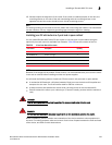
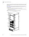
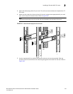
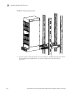
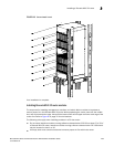
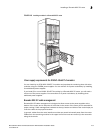
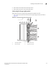
FIGURE 148 Installing a module in a Brocade MLX-32 router
Power supply requirements for NI-MLX-1Gx48-T-A modules
You can install up to 20 NI-MLX-1Gx48-T-A modules and populate the remaining slots with other
modules using four 2400W power supplies. You can achieve 4+4 power redundancy by installing
four additional power supplies.
If you install 21 or more NI-MLX-1Gx48-T-A modules in a Brocade MLX-32 router, you will need a
minimum of five power supplies. You can achieve 5+3 power redundancy by installing three
additional power supplies.
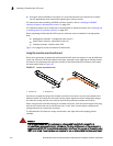
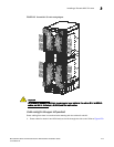
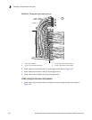
Brocade MLX-32 cable management
Brocade MLX-32 cable management is designed to allow access to the power supplies at the
bottom of the router, and to keep the air inlet clear in the center of the router (this is essential for
proper cooling). Cable management hardware at the top, bottom and sides of the router helps you
route the cables in the proper directions.
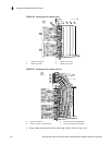
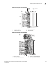
In general, cables from the outer interface modules are routed horizontally away from the router.
Cables from the remaining modules in the upper half of the router are routed up, then outwards
along the channels.
Pwr
Active
Pwr
Activ e
Pwr
Active
Pwr
Activ e
Pwr
Active
Pwr
Active
Pwr
Activ e
Pwr
Activ e
Pwr
Acti ve