


212 Brocade MLX Series and Brocade NetIron XMR Hardware Installation Guide53-1002373-02
Installing a Brocade MLX-32 router
3
a. Use the show running-config command in config mode to determine the current
configuration of the slot.
Brocade(config)# show running-config
Current configuration:
!
ver V5.0.0T163
module 1 ni-mlx-20-port-1g-copper
!
This example shows that slot 1 has already been configured for a 20-port 1g copper
interface module.
b. With the module designation from show running-config command output, use the no
module command to remove the configuration from slot 1.
Brocade(config)# no module 1 ni-mlx-20-port-1g-copper
This example removes the configuration from slot 1, leaving it ready for a new module.
2. Put on the ESD wrist strap and ground yourself by inserting the plug into the ESD connector on
the front of the router.
3. Remove the module from the packaging.
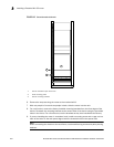
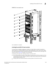
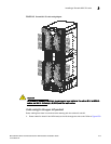
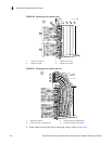
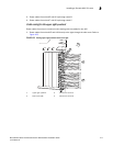
4. Insert the module into the router slot, and slide the card along the card guide until the ejectors
on either side of the module rotate towards the module faceplate. Refer to Figure 148.
NOTE
When inserting the module into the router, make sure that the faceplate does not overlap the
faceplate of an adjacent module.
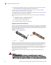
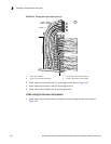
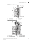
5. Rotate the ejectors until they are flush with the module faceplate. This action will fully seat the
module in the backplane.
6. Tighten the screws at each end of the module faceplate by pushing them in and turning them
clockwise. Complete the tightening process using the flat-blade screwdriver.
7. Enter the write memory command to ensure that the slot will be correctly configured for the
new module after a reboot.
Brocade(config)# write memory
Write startup-config done.