


Brocade MLX Series and Brocade NetIron XMR Hardware Installation Guide 189
53-1002373-02
Installing a Brocade MLX-16 router
3
Follow these steps to connect a DC power source.
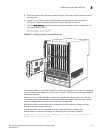
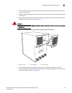
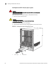
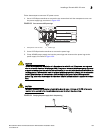
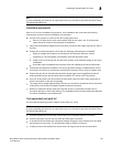
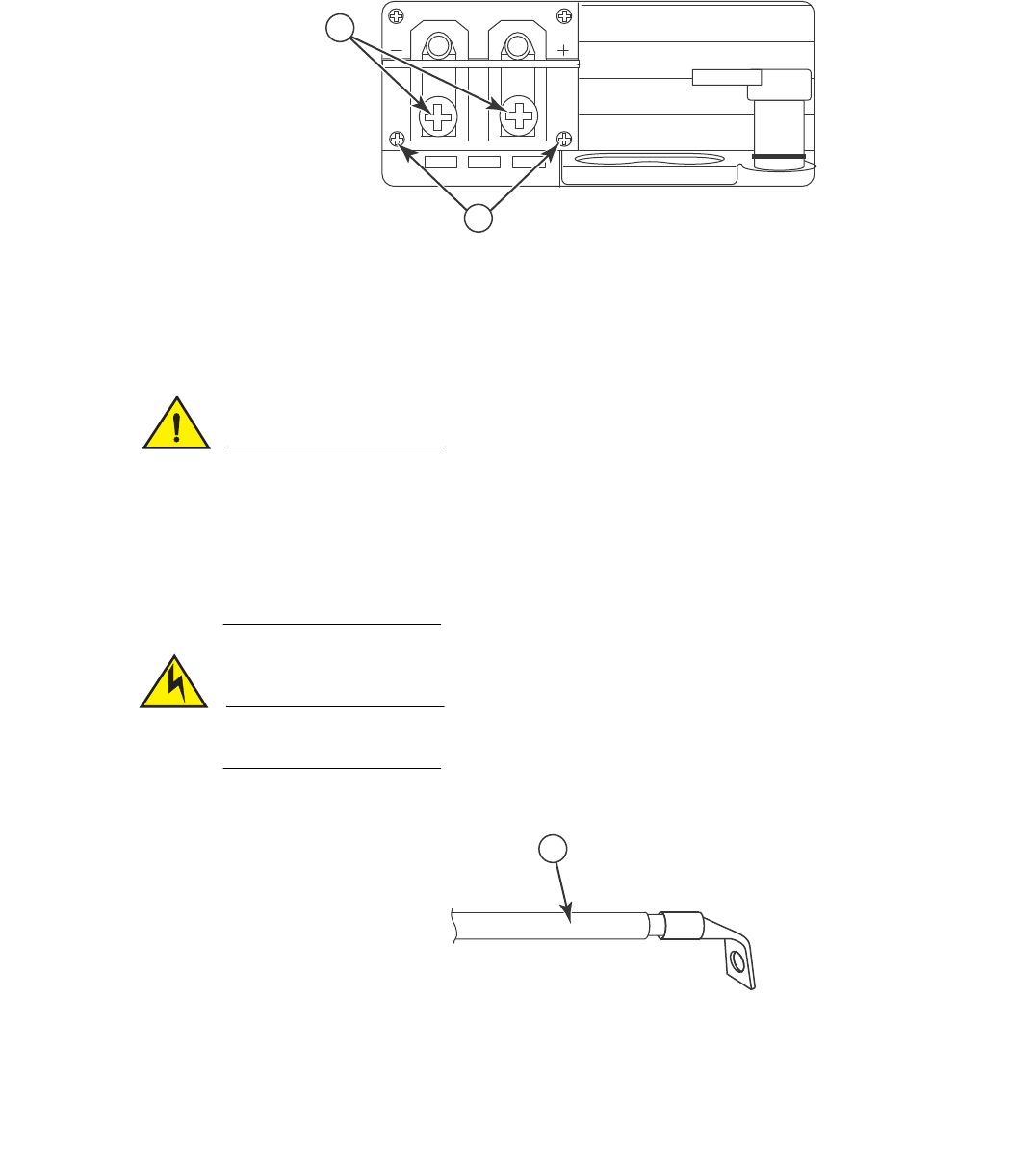
1. Use a #1 Phillips screwdriver to remove the two screws that hold the transparent cover over
the power supply lugs, as shown in Figure 133.
FIGURE 133 Cover screws and DC power lugs
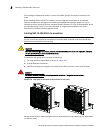
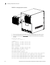
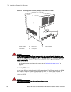
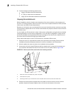
2. Use a #2 Phillips head screwdriver to remove the power lugs.
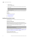
3. Crimp #8 AWG power supply wire into the power lugs and reconnect the power lugs to the
power supply unit. Refer to Figure 134.
CAUTION
For the NEBS-compliant installation of a Brocade router with AC and DC systems, use a ground
wire of at least 6 American Wire Gauge (AWG). The ground wire should have an agency-approved
crimped connector (provided with the device) attached to one end, with the other end attached to
building ground. The connector must be crimped with the proper tool, allowing it to be connected
to both ground screws on the enclosure. Before crimping the ground wire into the provided
ground lug, ensure the bare copper wire has been cleaned and antioxidant is applied to the bare
wire.
CAUTION
To ensure adequate bonding when attaching the ground lug, a minimum of 20 PSI of torque is
required to be applied to the mounting hardware used to attach the ground lug.
FIGURE 134 Crimping the power supply wire in the power lug
1 Transparent cover screws 2 Power lugs
DC OUT
ALM
DC IN
1
2
1