


Brocade MLX Series and Brocade NetIron XMR Hardware Installation Guide 247
53-1002373-02
Installing a Brocade NetIron XMR 4000 router
4
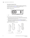
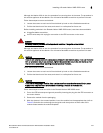
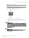
Although slot blanks differ in size, the procedure for removing them is the same. The procedure in
this section applies to all slot blanks. You will need a flat-blade screwdriver to perform this task.
Follow these steps to remove a slot blank:
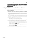
1. Loosen the screws on each end of the slot blank by hand or with a flat-blade screwdriver.
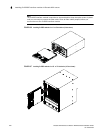
2. Pull the slot blank out of the router, and store it in a safe place for future use.
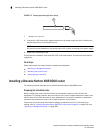
Before installing modules in the Brocade NetIron XMR 4000 router, have these items available:
• A large flat blade screwdriver.
• An ESD wrist strap with a plug for connection to the ESD connector on the router.
DANGER
For safety reasons, the ESD wrist strap should contain a 1 megohm series resistor.
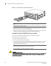
Although slot blanks differ in size, the procedure for removing them is the same. The procedure in
this section applies to all slot blanks. You will need a flat-blade screwdriver to perform this task.
CAUTION
If you do not install a module in a slot, you must keep the slot blank in place. If you run the router
with an uncovered slot, it may overheat. Tighten the screws that secure the slot blanks so that
they remain in place when removing adjacent panels or modules.
Follow these steps to remove a slot blank.
1. Loosen the screws on each end of the slot blank by hand or with a flat-blade screwdriver.
2. Pull the slot blank out of the router, and store it in a safe place for future use.
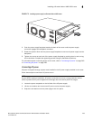
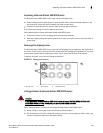
CAUTION
If you are hot-swapping a module, allow a minimum of two seconds after a module (or power
supply or fan tray) has been removed before inserting a module in the same slot.
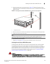
Follow these steps to install a module in the Brocade NetIron XMR 4000 router.
1. Put on the ESD wrist strap and ground yourself by inserting the plug into the ESD connector on
the router chassis.
2. Remove the module from the packaging.
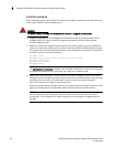
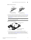
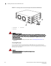
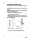
3. With the ejectors in the outward position, insert the module into the appropriate slot (refer to
Table 40) and slide the card along the card guide until the ejectors on either side of the
module rotate towards the module faceplate.