


Brocade MLX Series and Brocade NetIron XMR Hardware Installation Guide 391
53-1002373-02
Port specifications for all router models
9
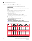
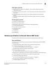
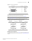
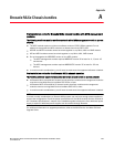
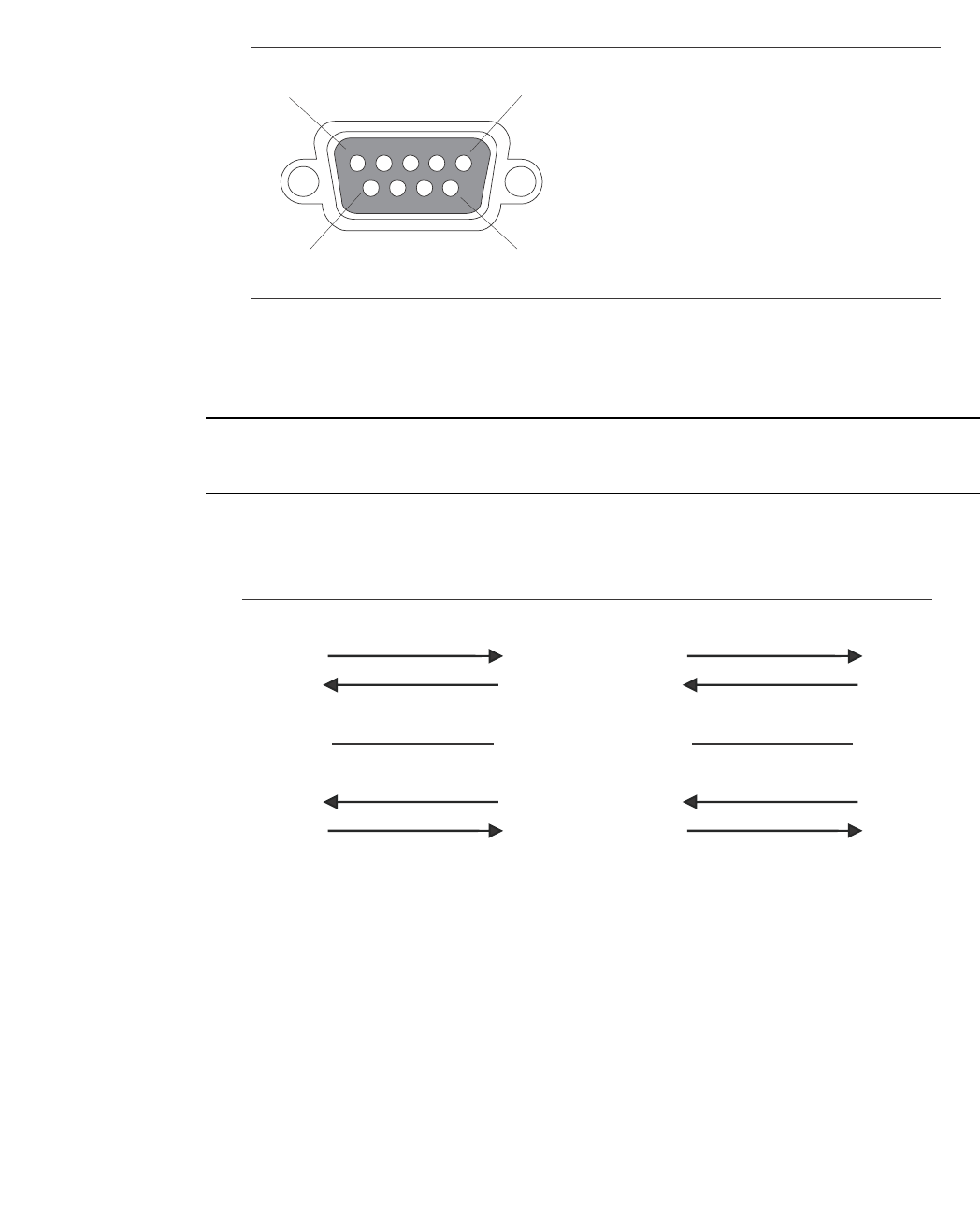
FIGURE 252 Console port pin and signalling details
Most PC serial ports require a cable with a female DB-9 connector. Terminal connections will vary,
requiring a cable with either a DB-9 or DB-25 connector, male or female.
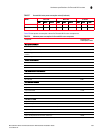
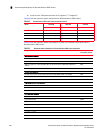
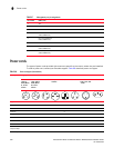
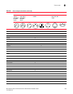
Serial cable options between the router and a PC or terminal are shown in Figure 253.
NOTE
As shown in Figure 252 and Figure 253, some wires should not be connected. If you connect wires
that are labeled “Reserved”, you may experience unexpected results with some terminals.
FIGURE 253 Console port pin assignments with connection options to a terminal or PC
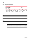
Management port pin assignments
The management port is an RJ45 UTP connector. Table 67 describes the pin assignments for this
connector. For information about how you can use this port, refer to “10/100/1000 Ethernet port”
on page 20.
1
5
96
Pin Assignment
DB-9 male
Pin Number
1
2
3
4
5
6
7
8
9
Switch Signal
Reserved
TXD (output)
RXD (input)
GND
CTS (input)
RTS (output)
Reserved
Reserved
Reserved
1
2
3
4
5
6
7
8
9
1
2
3
4
5
6
7
8
9
1
2
3
4
5
6
7
8
9
8
3
2
20
7
6
4
5
22
Reserved
DB-9 to DB-9
Female Switch
DB-9 to DB-25
Female Switch
Reserved
Reserved
Reserved
Reserved
Reserved
Reserved
Reserved
Terminal or PC Terminal or PC