


Brocade MLX Series and Brocade NetIron XMR Hardware Installation Guide 37
53-1002373-02
Router modules
1
NOTE
When you install BR-MLX-1GCx24-X modules, you must upgrade the software on all interface
modules and management modules to the appropriate software release. For more information on
the appropriate software release refer to the Hardware Installation Notes that shipped with the
modules.
NOTE
When you are replacing older modules with 24x1G modules, you must first delete the software
configuration for the older module. If you do not delete the old configuration, a configuration
mismatch will occur when you install the new module. This mismatch will be displayed in the results
of the show config command.
NOTE
The SNMP Management Information Base (MIB) uses the Interface Index (ifIndex) to assign a unique
value to each port on a module or slot. The number of indexes that can be assigned per module is
20, 40, or 64, depending on the number of ports on the module. When installing 24-port copper or
fiber interface modules, you must change the ifIndex allocation to 64 before you install the module,
or the module will not operate properly.
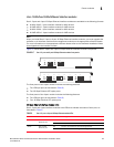
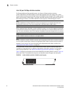
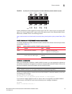
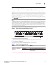
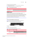
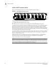
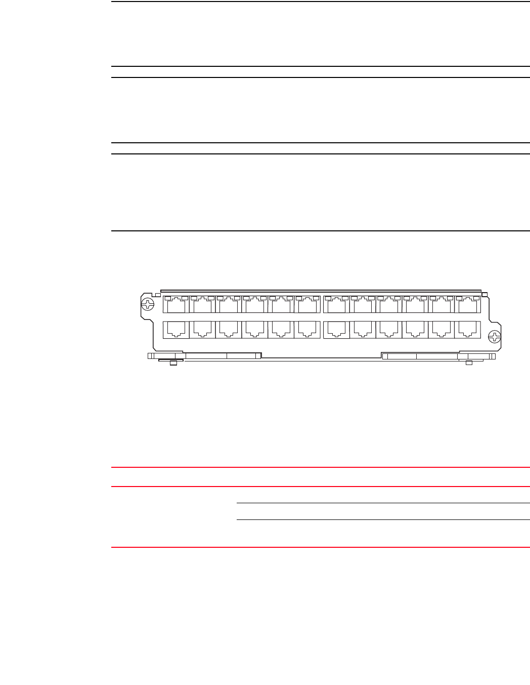
Figure 21 shows the front panel of the BR-MLX-1GCx24-X interface module.
FIGURE 21 BR-MLX-1GCx24-X copper interface module front panel
The front panel includes the following features:
• LEDs to the left support the top ports, LEDs to the right support the bottom ports
• 24 1 Gbps RJ45 copper ports
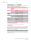
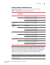
Table 15 describes the LEDs for the BR-MLX-1GCx24-X interface module.
TABLE 15 BR-MLX-1GCx24-X copper module LEDs
Position State Meaning
LEDs located at top right and
left edge of top row ports. Left
LED for top port, right LED for
bottom port)
Solid green A link has been established.
Green blinking The port is transmitting and receiving packets.
Off No link exists and the port is not transmitting or
receiving packets.