


46 Brocade MLX Series and Brocade NetIron XMR Hardware Installation Guide
53-1002373-02
Router modules
1
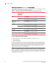
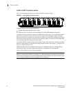
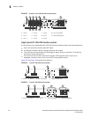
FIGURE 28 8-port OC-12c and OC-48c POS interface module
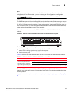
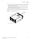
Single-Speed OC-192c POS interface modules
The front panel of the single-speed OC-192c POS interface modules contain the following features:
• One or two ports that accommodate XFP optics.
• An LED that indicates if power is being received by the module.
• Four LEDs per port that indicate the following port status: Active or Local Rail, TX Pkt, RX Pkt,
and Carrier Rcvd or Remote Fail.
• Two IN and two OUT RJ-48C connectors to provide a BITS external clock source and to
propagate a common clock source (Line or BITS) among POS modules.
Figure 29, and Figure 30 illustrate these features.
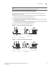
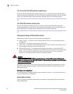
FIGURE 29 1-port OC-192c POS interface module
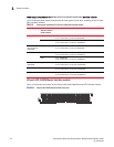
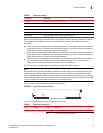
FIGURE 30 2-port OC-192c POS interface module
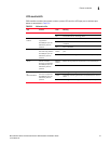
1 Power 4 Port 3 7 Port 6 10 Port status LEDs
2 Port 1 5 Port 4 8 Port 7 11 BITS clocking ports
3 Port 2 6 Port 5 9 Port 8
1 Power 2 Port 1 3 Port status LEDs 4 ZBITS clocking ports
1 Power 2 Port 1 3 Port 2 4 Port status LEDs 5 BITS clocking ports
Power
Active /
Local Fail
Tx Pk
t
BITS1
BITS2
Rx Pkt
Carrier Rcvd /
Remote Fail
I
N
O
U
T
1234 5678
1
2
3
4
5
6
7
8
I
N
O
U
T
2 4 6 8
1
10
11
3 5 7 9
Power
Active /
Local Fail
Tx Pk
t
BITS1
BITS2
Rx Pkt
Carrier Rcvd /
Remote Fail
I
N
O
U
T
1
I
N
O
U
T
1
1
2
3
4
Power
Active /
Local Fail
Tx Pk
t
BITS1
BITS2
Rx Pkt
Carrier Rcvd /
Remote Fail
I
N
O
U
T
12
I
N
O
U
T
1
2
1
2
3
4
5