


214 Brocade MLX Series and Brocade NetIron XMR Hardware Installation Guide53-1002373-02
Installing a Brocade MLX-32 router
3
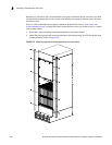
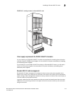
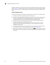
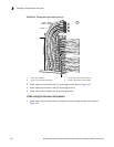
Cables for modules in the lower half of the router follow a similar path downwards, above the power
supplies. Figure 149 shows the cable routing, with the upper and lower cable management system
covers removed for clarity. The following sections describe cable routing for each quadrant of the
router.
Cable management notes
The following rules apply when setting up cable management for a heavily- or fully-loaded system:
• All cables must be firmly connected, supported, and contained.
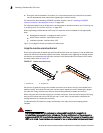
• Use cable cinches, spaced approximately every 24 inches, to secure all of the cables for each
module into a single bundle. This is especially important at the ends nearest the module
connections. Each cable cinch holds up to 8 MRJ21 cables, or 48 RJ45 cables.
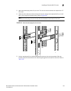
• For additional security, use cable ties to secure cables to the cable management system
hardware on the sides of the unit (Refer to Figure 1.8).
• The cable routing slots at the top and bottom of the unit are strong enough to hold many
cables, but the more cable cinches and cable ties you use, the more secure your cable
management system will be.
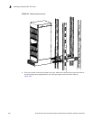
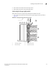
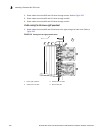
• If you bundle the cables correctly, you will be able to move the bundles to the side to access
the modules for service, without disturbing the connections. Refer to Figure 158.
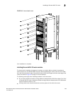
• Always route the cables for the outer-most modules out the sides of the unit. Route the cables
for the innermost modules through the top or through the bottom cable management hardware
on the unit.