


9-5
Cisco ME 3400 Ethernet Access Switch Software Configuration Guide
OL-9639-06
Chapter 9 Configuring Interfaces
Understanding Interface Types
Note IEEE 802.1Q tunneling is only supported when the switch is running the metro IP access or metro access
image.
Tunnel ports cannot be trunk ports or access ports and must belong to a VLAN unique to each customer.
For more information about tunnel ports, see Chapter 13, “Configuring IEEE 802.1Q and Layer 2
Protocol Tunneling.”
Routed Ports
A routed port is a physical port that acts like a port on a router; it does not have to be connected to a
router. A routed port is not associated with a particular VLAN, as is an access port. A routed port behaves
like a regular router interface, except that it does not support VLAN subinterfaces. Routed ports can be
configured with a Layer 3 routing protocol. A routed port is a Layer 3 interface only and does not support
Layer 2 protocols, such as STP.
Configure routed ports by putting the interface into Layer 3 mode with the no switchport interface
configuration command. Then assign an IP address to the port, enable routing, and assign routing
protocol characteristics by using the ip routing and router protocol global configuration commands.
Note Entering a no switchport interface configuration command shuts down the interface and then re-enables
it, which might generate messages on the device to which the interface is connected. When you put an
interface that is in Layer 2 mode into Layer 3 mode, the previous configuration information related to
the affected interface might be lost.
The number of routed ports that you can configure is not limited by software. However, the
interrelationship between this number and the number of other features being configured might impact
CPU performance because of hardware limitations. See the
“Configuring Layer 3 Interfaces” section on
page 9-22 for information about what happens when hardware resource limitations are reached.
For more information about IP unicast and multicast routing and routing protocols, see Chapter 35,
“Configuring IP Unicast Routing” and Chapter 40, “Configuring IP Multicast Routing.”
Note For full Layer 3 routing, you must have the metro IP access image installed on the switch
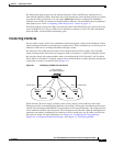
Switch Virtual Interfaces
A switch virtual interface (SVI) represents a VLAN of switch ports as one interface to the routing or
bridging function in the system. Only one SVI can be associated with a VLAN, but you need to configure
an SVI for a VLAN only when you wish to route between VLANs or to provide IP host connectivity to
the switch. By default, an SVI is created for the default VLAN (VLAN 1) to permit remote switch
administration. Additional SVIs must be explicitly configured.
Note You cannot delete interface VLAN 1.
SVIs provide IP host connectivity only to the system; in Layer 3 mode, you can configure routing across
SVIs.