


36-4
Cisco ME 3400 Ethernet Access Switch Software Configuration Guide
OL-9639-06
Chapter 36 Configuring HSRP
Understanding HSRP
HSRPv2 has a different packet format than HSRPv1. A HSRPv2 packet uses the
type-length-value (TLV) format and has a 6-byte identifier field with the MAC address of the
physical router that sent the packet.
If an interface running HSRPv1 gets an HSRPv2 packet, the type field is ignored.
HSRPv2 and HSRPv1 are mutually exclusive. HSRPv2 is not interoperable with HSRPv1 on an interface
and the reverse.
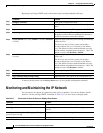
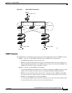
Multiple HSRP
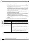
The switch supports Multiple HSRP (MHSRP), an extension of HSRP that allows load sharing between
two or more HSRP groups. You can configure MHSRP to achieve load balancing and to use two or more
standby groups (and paths) from a host network to a server network. In
Figure 36-2, half the clients are
configured for Router A, and half the clients are configured for Router B. Together, the configuration for
Routers A and B establishes two HSRP groups. For group 1, Router A is the default active router because
it has the assigned highest priority, and Router B is the standby router. For group
2, Router B is the
default active router because it has the assigned highest priority, and Router A is the standby router.
During normal operation, the two routers share the IP traffic load. When either router becomes
unavailable, the other router becomes active and assumes the packet-transfer functions of the router that
is unavailable.
See the “Configuring MHSRP” section on page 36-10 for the example configuration steps.
Note For MHSRP, you need to enter the standby preempt interface configuration command on the HSRP
interfaces so that if a router fails and then comes back up, preemption restores load sharing.
Figure 36-2 MHSRP Load Sharing
121235
Active router for group 1
Standby router for group 2
Client 1
Router A Router B
10.0.0.1 10.0.0.2
Active router for group 2
Standby router for group 1
Client 2 Client 3 Client 4