


14-4
Cisco ME 3400 Ethernet Access Switch Software Configuration Guide
OL-9639-06
Chapter 14 Configuring STP
Understanding Spanning-Tree Features
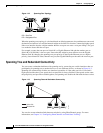
• The shortest distance to the root switch is calculated for each switch based on the path cost.
• A designated switch for each LAN segment is selected. The designated switch incurs the lowest path
cost when forwarding packets from that LAN to the root switch. The port through which the
designated switch is attached to the LAN is called the designated port. For the Cisco ME switch, this
only applies to NNIs or to ENIs on which STP has been specifically enabled.
All paths that are not needed to reach the root switch from anywhere in the switched network are placed
in the spanning-tree blocking mode.
Bridge ID, Switch Priority, and Extended System ID
The IEEE 802.1D standard requires that each switch has an unique bridge identifier (bridge ID), which
controls the selection of the root switch. Because each VLAN is considered as a different logical bridge
with PVST+ and rapid PVST+, the same switch must have as many different bridge IDs as VLANs
configured on it. Each VLAN on the switch has a unique 8-byte bridge ID. The two most-significant
bytes are used for the switch priority, and the remaining six bytes are derived from the switch MAC
address.
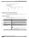
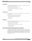
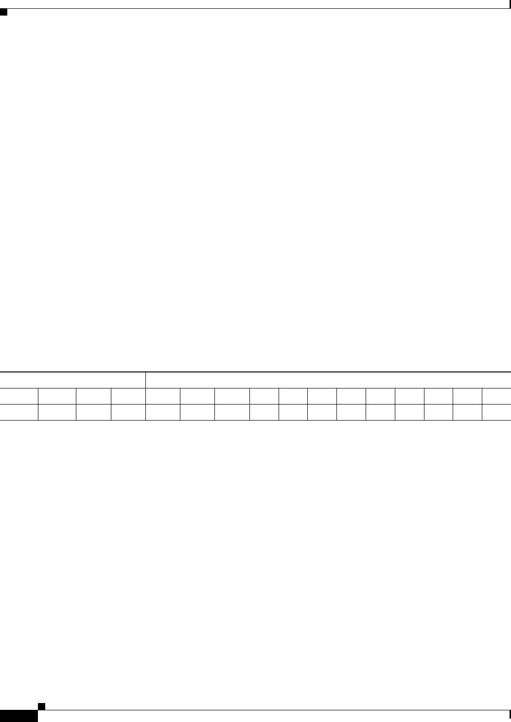
The switch supports the IEEE 802.1t spanning-tree extensions, and some of the bits previously used for
the switch priority are now used as the VLAN identifier. The result is that fewer MAC addresses are
reserved for the switch, and a larger range of VLAN IDs can be supported, all while maintaining the
uniqueness of the bridge ID. As shown in
Table 14-1, the two bytes previously used for the switch
priority are reallocated into a 4-bit priority value and a 12-bit extended system ID value equal to the
VLAN ID.
Spanning tree uses the extended system ID, the switch priority, and the allocated spanning-tree MAC
address to make the bridge ID unique for each VLAN.
Support for the extended system ID affects how you manually configure the root switch, the secondary
root switch, and the switch priority of a VLAN. For example, when you change the switch priority value,
you change the probability that the switch will be elected as the root switch. Configuring a higher value
decreases the probability; a lower value increases the probability. For more information, see the
“Configuring the Root Switch” section on page 14-15, the “Configuring a Secondary Root Switch”
section on page 14-17, and the “Configuring the Switch Priority of a VLAN” section on page 14-20.
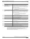
Spanning-Tree Interface States
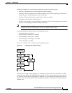
Propagation delays can occur when protocol information passes through a switched LAN. As a result,
topology changes can take place at different times and at different places in a switched network. When
an STP port transitions directly from nonparticipation in the spanning-tree topology to the forwarding
state, it can create temporary data loops. Interfaces must wait for new topology information to propagate
through the switched LAN before starting to forward frames. They must allow the frame lifetime to
expire for forwarded frames that have used the old topology.
Ta ble 14-1 Switch Priority Value and Extended System ID
Switch Priority Value Extended System ID (Set Equal to the VLAN ID)
Bit 16 Bit 15 Bit 14 Bit 13 Bit 12 Bit 11 Bit 10 Bit 9 Bit 8 Bit 7 Bit 6 Bit 5 Bit 4 Bit 3 Bit 2 Bit 1
32768 16384 8192 4096 2048 1024 512 256 128 64 32 16 8 4 2 1