


35-77
Cisco ME 3400 Ethernet Access Switch Software Configuration Guide
OL-9639-06
Chapter 35 Configuring IP Unicast Routing
Configuring Multi-VRF CE
To configure VRF, you create a VRF table and specify the Layer 3 interface associated with the VRF.
Then configure the routing protocols in the VPN and between the CE and the PE. BGP is the preferred
routing protocol used to distribute VPN routing information across the provider’s backbone. The
multi-VRF CE network has three major components:
• VPN route target communities—lists of all other members of a VPN community. You need to
configure VPN route targets for each VPN community member.
• Multiprotocol BGP peering of VPN community PE routers—propagates VRF reachability
information to all members of a VPN community. You need to configure BGP peering in all PE
routers within a VPN community.
• VPN forwarding—transports all traffic between all VPN community members across a VPN
service-provider network.
Default Multi-VRF CE Configuration
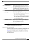
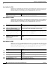
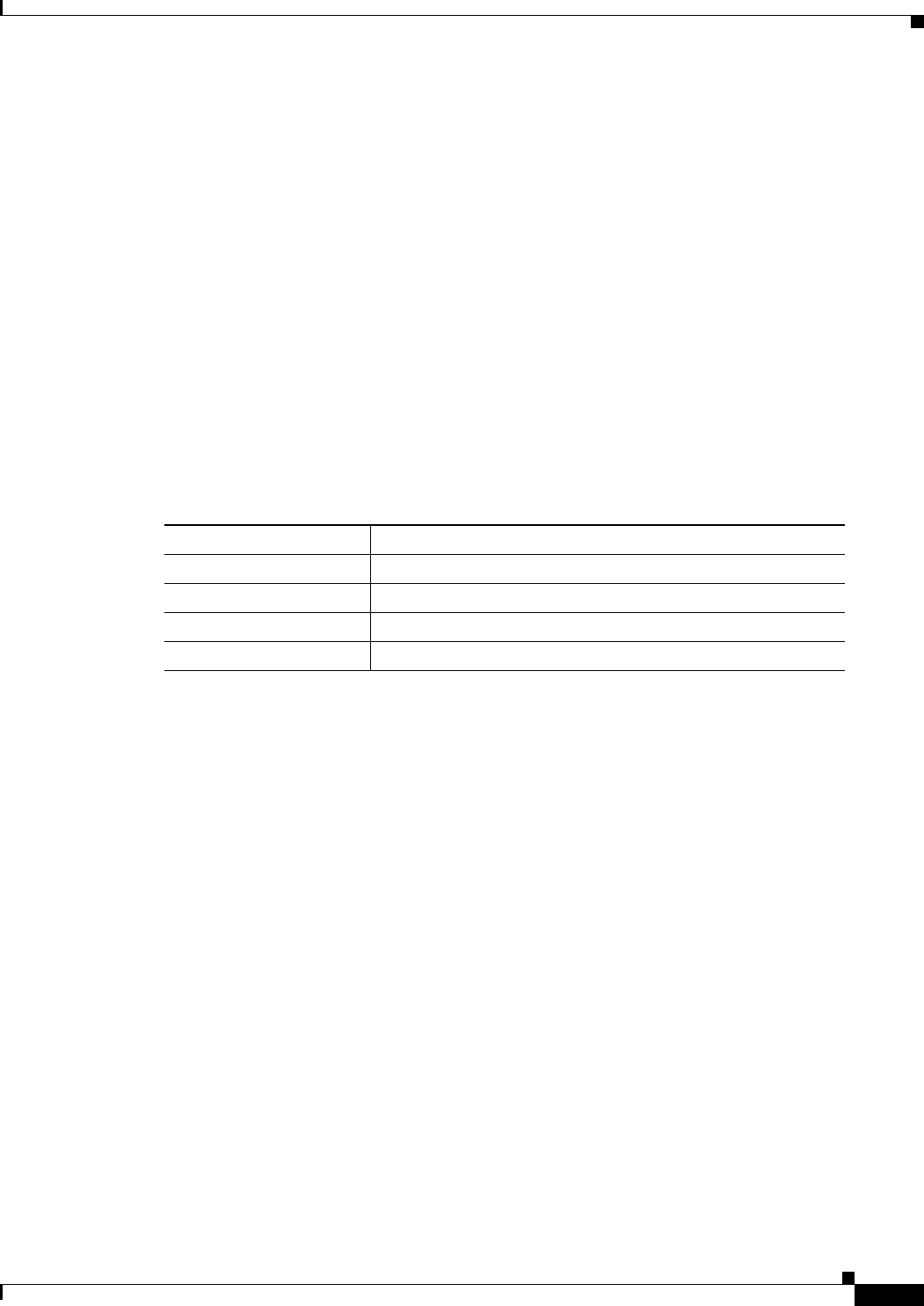
Table 35-14 shows the default VRF configuration.
Multi-VRF CE Configuration Guidelines
These are considerations when configuring VRF in your network:
• A switch with multi-VRF CE is shared by multiple customers, and each customer has its own routing
table.
• Because customers use different VRF tables, the same IP addresses can be reused. Overlapped IP
addresses are allowed in different VPNs.
• Multi-VRF CE lets multiple customers share the same physical link between the PE and the CE.
Trunk ports with multiple VLANs separate packets among customers. Each customer has its own
VLAN.
• Multi-VRF CE does not support all MPLS-VRF functionality. It does not support label exchange,
LDP adjacency, or labeled packets.
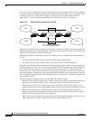
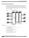
• For the PE router, there is no difference between using multi-VRF CE or using multiple CEs. In
Figure 35-6, multiple virtual Layer 3 interfaces are connected to the multi-VRF CE device.
• The switch supports configuring VRF by using physical ports, VLAN SVIs, or a combination of
both. The SVIs can be connected through an access port or a trunk port.
• A customer can use multiple VLANs as long as they do not overlap with those of other customers.
A customer’s VLANs are mapped to a specific routing table ID that is used to identify the
appropriate routing tables stored on the switch.
• The switch supports one global network and up to 26 VRFs.
Ta ble 35-14 Default VRF Configuration
Feature Default Setting
VRF Disabled. No VRFs are defined.
Maps No import maps, export maps, or route maps are defined.
VRF maximum routes 5000
Forwarding table The default for an interface is the global routing table.